Inverted tooth chain output transmission device for snow caster

A technology of transmission device and toothed chain, which is applied in the direction of transmission device, transmission chain, hoisting device, etc. It can solve the problems of easy slipping of V-belt transmission, easy damage of reducer transmission, high maintenance cost, etc., and achieve large torque and stable operation , The effect of large transmission torque

Inactive Publication Date: 2010-12-29
哈尔滨市环隆卫生工具厂
View PDF7 Cites 0 Cited by
  • Summary
  • Abstract
  • Description
  • Claims
  • Application Information

AI Technical Summary

Problems solved by technology

[0003] The purpose of the present invention is to solve the problems of V-belt transmission which are easy to slip, prone to fatigue, low transmission efficiency and small torque, and the problems of reducer transmission which are easy to be damaged, short life, low efficiency and high maintenance cost , and then provide a toothed chain output transmission device for a snow blower

Method used


Image

  • Inverted tooth chain output transmission device for snow caster
  • Inverted tooth chain output transmission device for snow caster
  • Inverted tooth chain output transmission device for snow caster

Examples


specific Embodiment approach 1

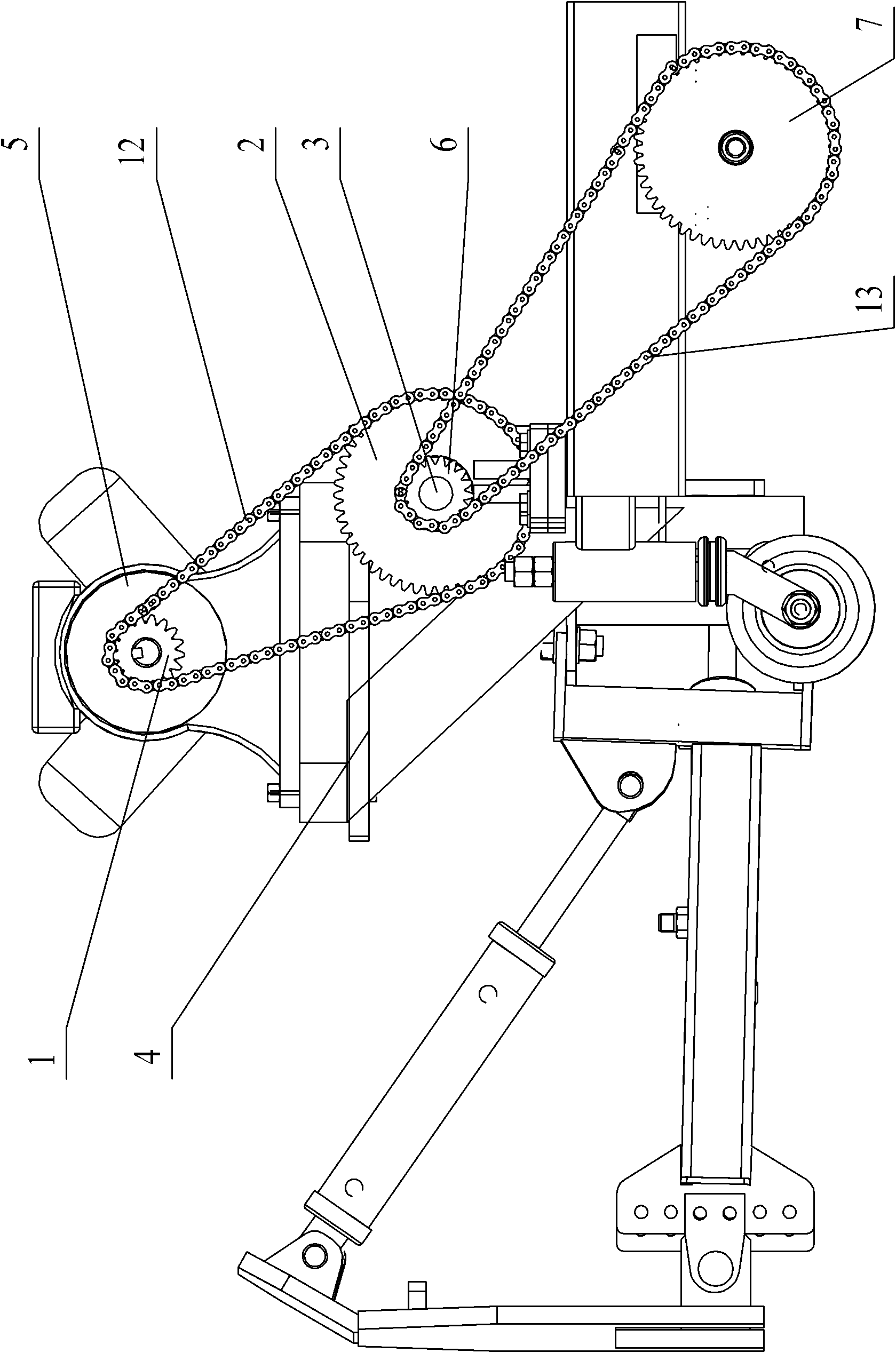
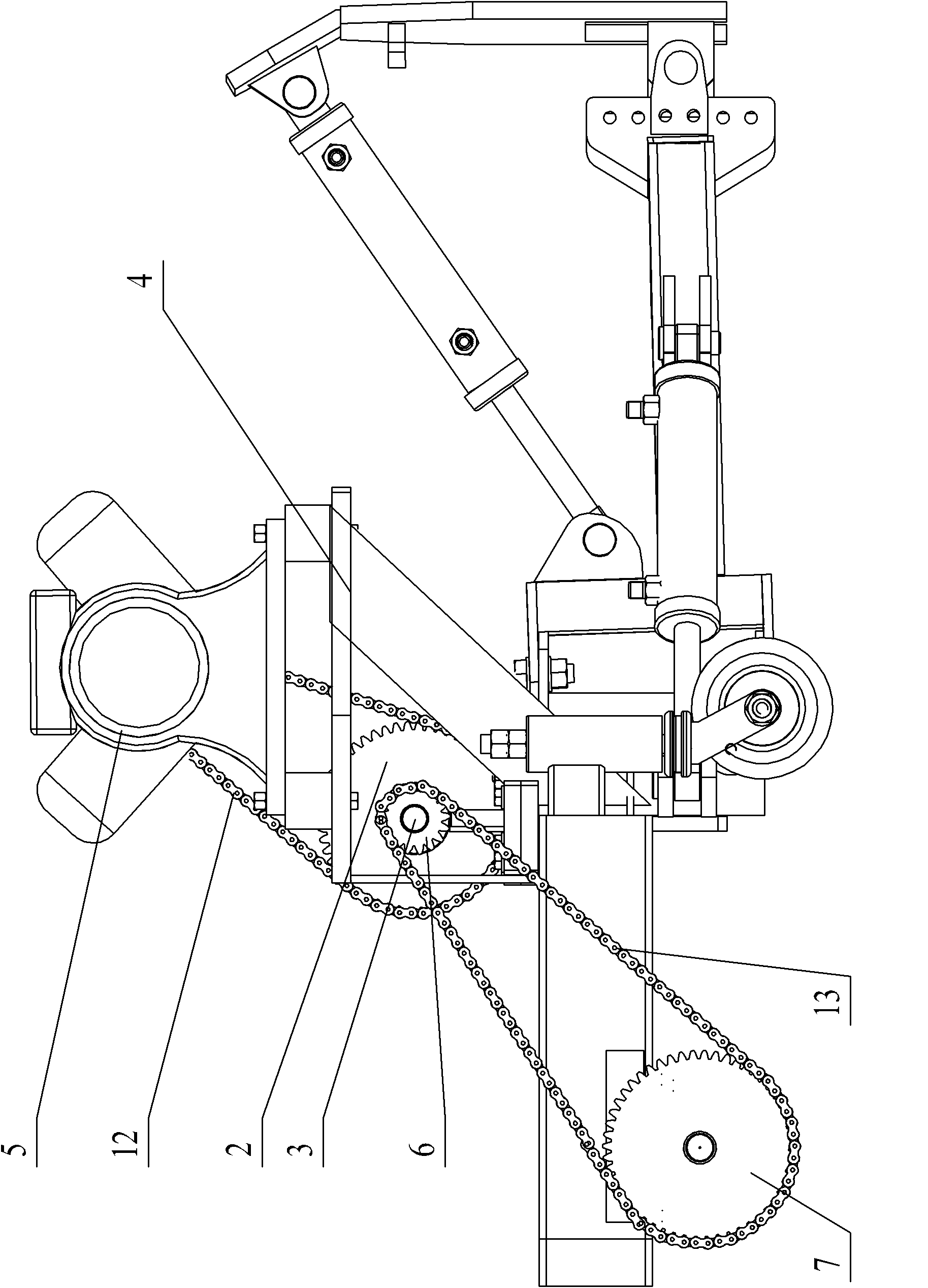
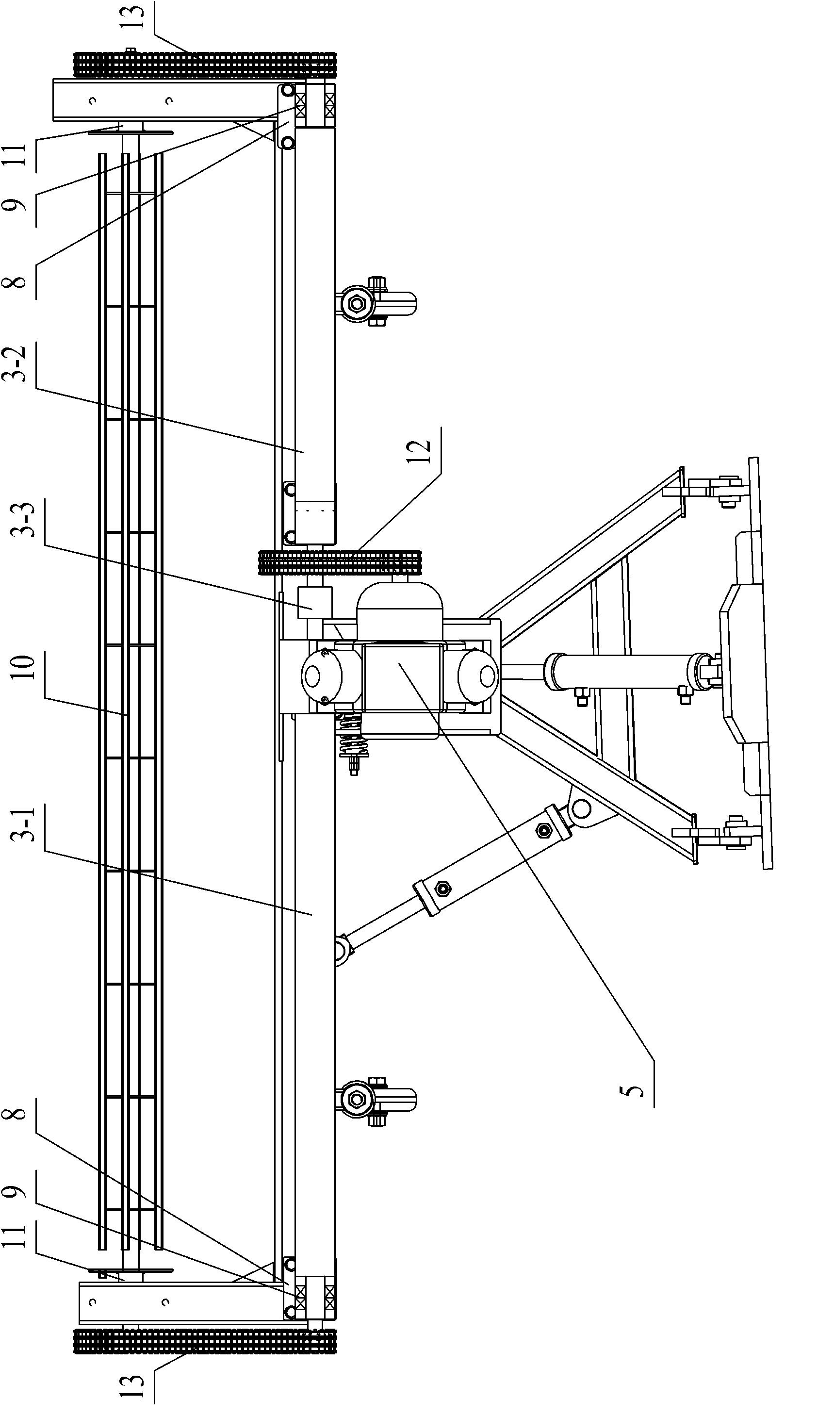
[0007] Specific implementation mode 1: Combination Figure 1-Figure 3 To explain this embodiment, the toothed chain output transmission device of the snow blower of this embodiment includes a main frame 4, and the output transmission device also includes a driving small toothed sprocket 1, a driven large toothed sprocket 2, a transmission shaft 3, Air-cooled dual-cylinder diesel engine 5, roller brush shaft 10, toothed chain 12, two small transmission sprockets 6, two large transmission sprockets 7, two bearing seats 8, two rolling bearings 9, two seated bearings 11 And two drive chains 13, the air-cooled double-cylinder diesel engine 5 is fixedly installed at the upper end of the main frame 4, and the output shaft of the air-cooled double-cylinder diesel engine 5 is fixedly installed with an active small toothed sprocket 1, the main frame 4 A bearing seat 8 is fixedly installed at the left and right ends of the drive shaft 3, and both ends of the transmission shaft 3 pass thro...

specific Embodiment approach 2

[0008] Specific implementation manner two: combination image 3 The present embodiment will be described. The rolling bearing 9 of the present embodiment is a double row rolling bearing. With this setting, the drive shaft has a small jump, running more smoothly, and reducing torque loss. The other composition and connection relationship are the same as in the first embodiment.

specific Embodiment approach 3

[0009] Specific implementation mode three: combination image 3 The present embodiment will be described. The seated bearing 11 of the present embodiment is a seated spherical ball bearing. This setting has the effect of adjusting the heart. Other components and connection relationships are the same as those in the first or second embodiment.


PUM


Abstract

The invention discloses an inverted tooth chain output transmission device for a snow caster, relates to an output transmission device for the snow caster, and solves the problems of easy slipping, easy fatigue stretching, low transmission efficiency and small torque of transmission of a vee belt, and easy damage, short service life, low efficiency and high maintenance cost of transmission of a reduction box. An air-cooled two-cylinder diesel engine is arranged on a main framework, and an output shaft of the air-cooled two-cylinder diesel engine is provided with a driving toothlet chain wheel; two ends of a transmission shaft pass through a bearing seat and are fixedly connected with a drive small chain wheel; a driven sprocket canine tooth chain wheel is arranged on the transmission shaft, and the driving toothlet chain wheel is in transmission connection with the driven sprocket canine tooth chain wheel through an inverted tooth chain; and a roller shaft is fixedly connected to the main framework through two pillow block bearings, two ends of the roller shaft pass through the corresponding pillow block bearings and are fixedly connected with a drive big chain wheel, and each drive small chain wheel is in transmission connection with the corresponding drive big chain wheel through a transmission chain. The inverted tooth chain output transmission device is suitable for the snow caster.

Description

Technical field [0001] The invention relates to an output transmission device of a snow blower, in particular to a toothed chain output transmission device of a snow blower. Background technique [0002] The existing snow blowers are all water-cooled diesel engines, and the output is driven by a V-belt or a reducer. The disadvantage is that the V-belt drive is easy to slip (especially in winter), high-speed rotation heat generates fatigue and stretch; the transmission efficiency is low, and the torque is small. At present, the maximum input speed of the domestic reducer is 1500r / min, and the water-cooled engine is 2200r / min. The transmission of the snow blower is driven by a single-sided universal joint shaft directly connected reducer, and the universal joint shaft does not have a bearing seat. The shaft has large runout, unevenness, and large torque loss, so it has the defects of easy damage, short life, low efficiency, and high maintenance cost. Summary of the invention [00...

Claims


Application Information

Patent Timeline
Patent Type & Authority Applications(China)
IPC IPC(8): E01H5/09F16H7/06F16H55/30F16G13/02
Inventor 和静伟房松令
Owner 哈尔滨市环隆卫生工具厂
Why Eureka
Try Eureka