Mounting substrate, and method for manufacturing thin light-emitting device using same

A technology for mounting substrates and manufacturing methods, applied in the direction of electrical components, electrical solid devices, circuits, etc., can solve problems such as hindering stability, burrs, short circuits, etc., and achieve the effect of easy handling

Inactive Publication Date: 2010-12-29
ELEMENT DENSHI
View PDF1 Cites 2 Cited by
  • Summary
  • Abstract
  • Description
  • Claims
  • Application Information

AI Technical Summary

Problems solved by technology

However, in this method, burrs may be generated because the conductive pattern is cut by a cutting blade rotating at high speed.
If a burr occurs as described above, it will not only damage the appearance, but also hinder the stability during installation, and may cause a short circuit after installation.

Method used


Image

  • Mounting substrate, and method for manufacturing thin light-emitting device using same
  • Mounting substrate, and method for manufacturing thin light-emitting device using same
  • Mounting substrate, and method for manufacturing thin light-emitting device using same

Examples


Embodiment Construction

[0040] Below, refer to Figure 1 to Figure 6 Embodiments of the present invention will be described.

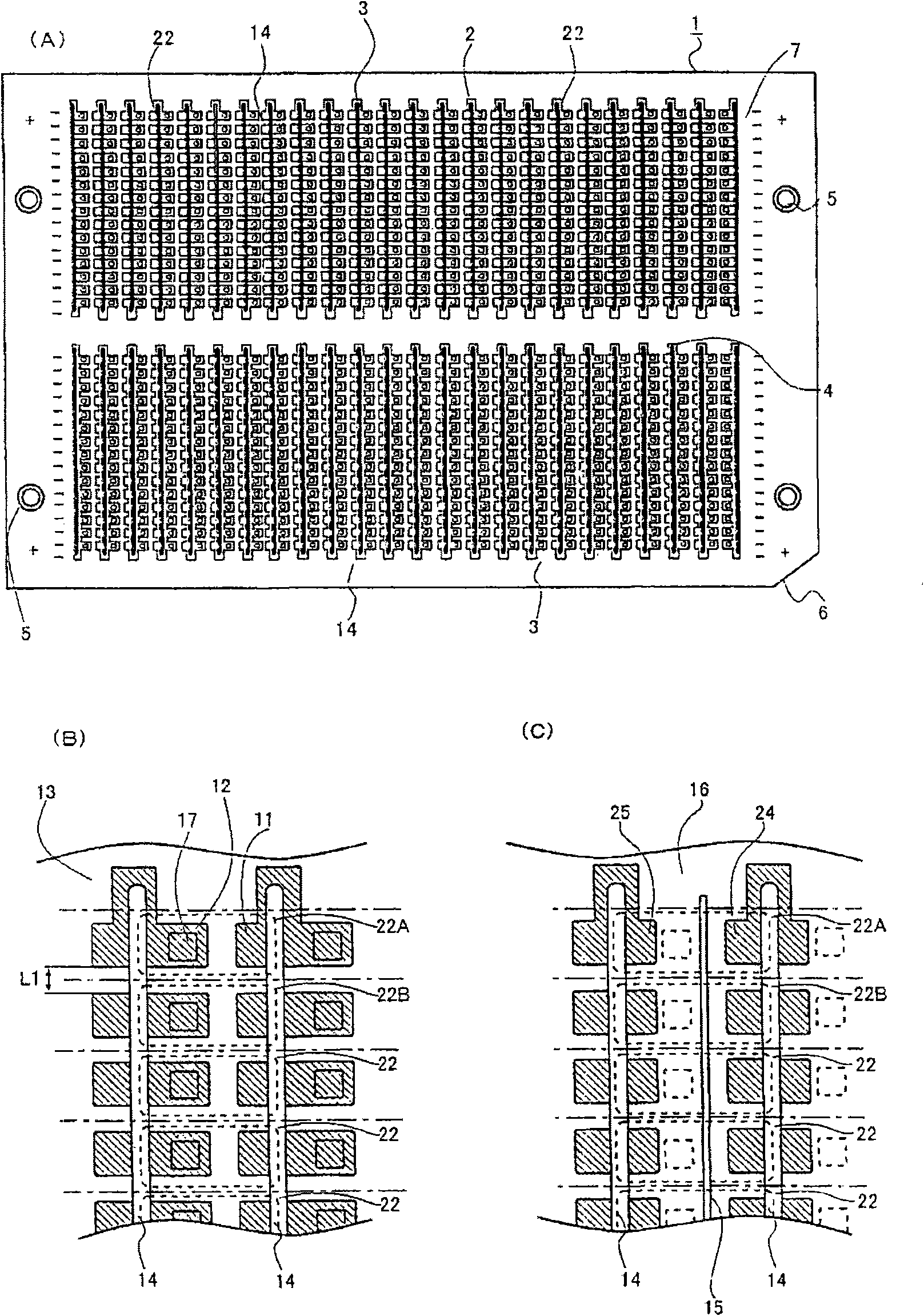
[0041] first, figure 1 Shows the mounting substrate of the present invention. figure 1 (A) is a plan view, figure 1 (B) is an enlarged view of the surface, figure 1 (C) is an enlarged view of the back side.

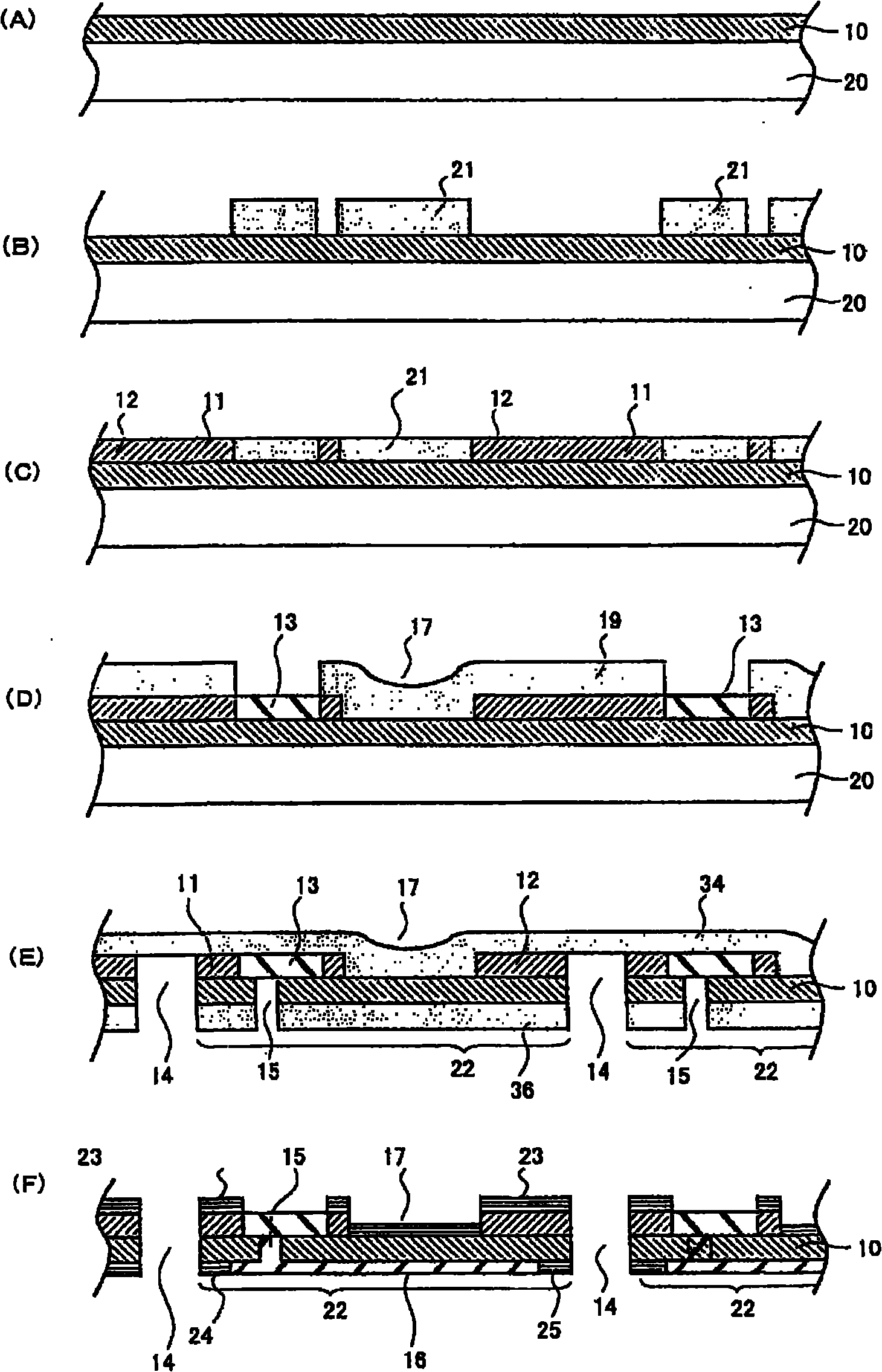
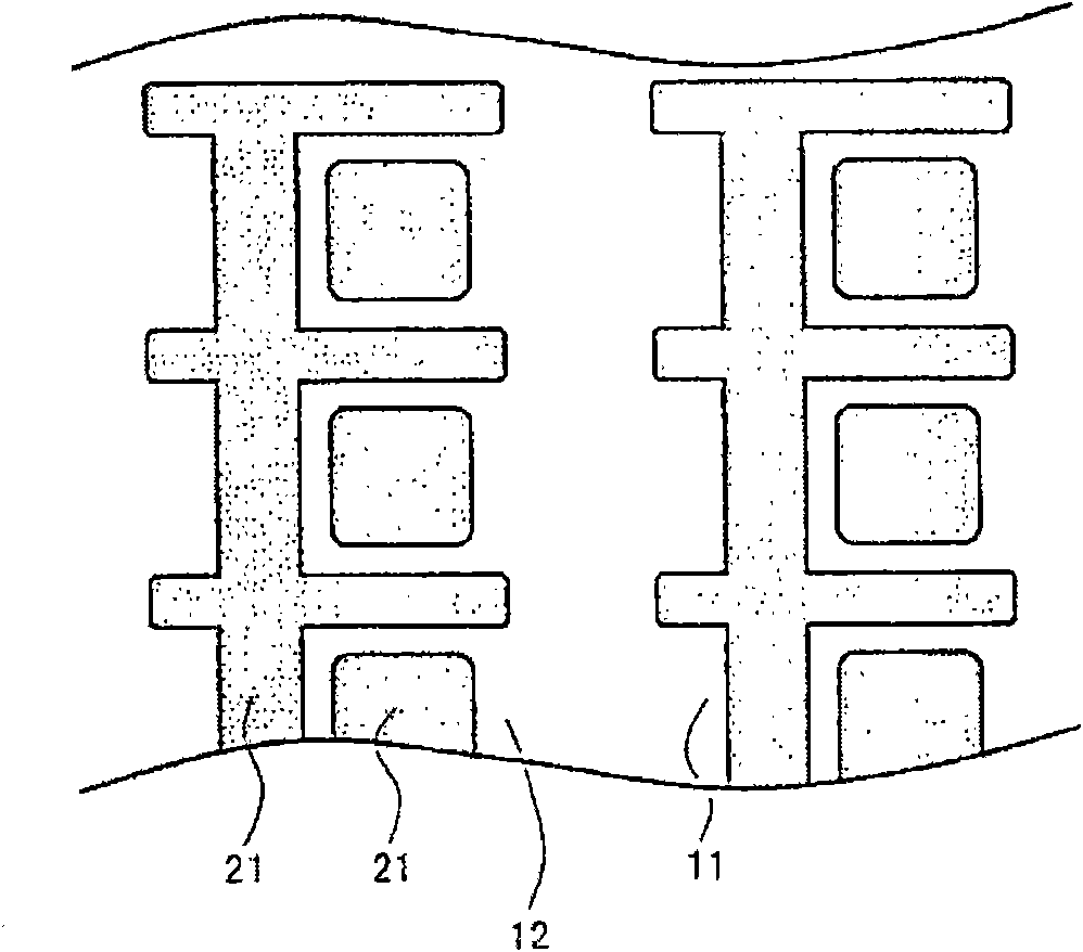
[0042] The mounting substrate 1 of this embodiment is composed of a conductive foil 10 , a first electrode portion 11 , a second electrode portion 12 , a liquid resin 13 , a separation slit 14 , an insulation slit 15 , and a solder resist layer 16 .

[0043] As the conductive foil 10 , a metal that can be etched and electrolytically plated is selected. In this embodiment, metal foil made of copper is used. Copper foils with extremely thin thicknesses such as 9 μm, 12 μm, 18 μm, and 35 μm are selected. This is because copper foils constitute the mounting substrate of thin light-emitting devices, so it is better to choose copper foils as thin as possible. If the...


PUM


Abstract

The invention provides a mounting substrate and a method for manufacturing thin light-emitting device using same, which is capable of inhibiting generation of burrs and realizing mass production of light-emitting device. In the mounting substrate of the invention, a conductive foil is removed at the edge of a unit. In particular, on the upper surface of the mounting substrate, a unit formed of a first electrode part and a second electrode part encircling a mounting part is formed, a plurality of units are arranged in columns. Furthermore, on the lower surface of the mounting substrate, a first external take-out electrode part connected with the first electrode is provided, and a second external take-out electrode part connected with the second electrode is provided. Besides, resin material for forming the mounting substrate, without the existence of conductive foil and other metal materials, is provided among the units. Therefore, in the manufacture of the light-emitting device, even if the mounting substrate between the units is cut off, the burr is not generated as the metal material is not cut off.

Description

technical field [0001] The present invention relates to a mounting substrate and a method for manufacturing a thin light-emitting device in which a light-emitting element is mounted on a mounting portion on a conductive foil using the mounting substrate. multiple electrodes. Background technique [0002] Figure 7 A light-emitting device is shown in which light emitted from a light-emitting element is prevented from being absorbed in a base substrate, and loss of light emission is suppressed to improve overall luminance. [0003] This light emitting device is composed of a light emitting element 100 , a base substrate 200 , a substrate electrode 300 , a connection electrode portion 400 , a light reflection portion 500 , a hole portion 600 , and a plating layer 700 . The light emitting element 100 is a Group III nitride compound semiconductor light emitting element. The base substrate 200 is an insulating substrate formed of resin such as polyimide, epoxy glass, or BT resin...

Claims


Application Information

Patent Timeline
Patent Type & Authority Applications(China)
IPC IPC(8): H01L23/498H01L33/48H01L33/62
CPCH01L24/97H01L2224/48091H01L2224/73265H01L2924/01322
Inventor 成田悟郎
Owner ELEMENT DENSHI
Why Eureka
Try Eureka