
Numerical control center sill combined drilling machine

A combined drilling machine and CNC spindle technology, applied in the parts of boring machine/drilling machine, drilling repair, drilling tool accessories, etc., can solve the problem of difficulty in guaranteeing tool durability, and achieve the effect of advanced tool selection, good workmanship and advanced structure

Inactive Publication Date: 2011-01-05
SHENYANG XINGYE MACHINE TOOL
View PDF4 Cites 19 Cited by
  • Summary
  • Abstract
  • Description
  • Claims
  • Application Information

AI Technical Summary

Problems solved by technology

Due to the limitation of the process method and the structure of the machine tool, coolant cannot be added to the hole, and the burning of the drill bit often occurs, and the durability of the tool is difficult to guarantee.

Method used


Image

  • Numerical control center sill combined drilling machine
  • Numerical control center sill combined drilling machine
  • Numerical control center sill combined drilling machine

Examples


Embodiment Construction

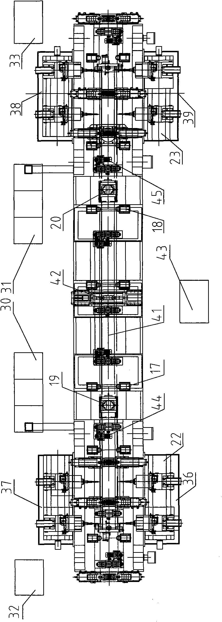
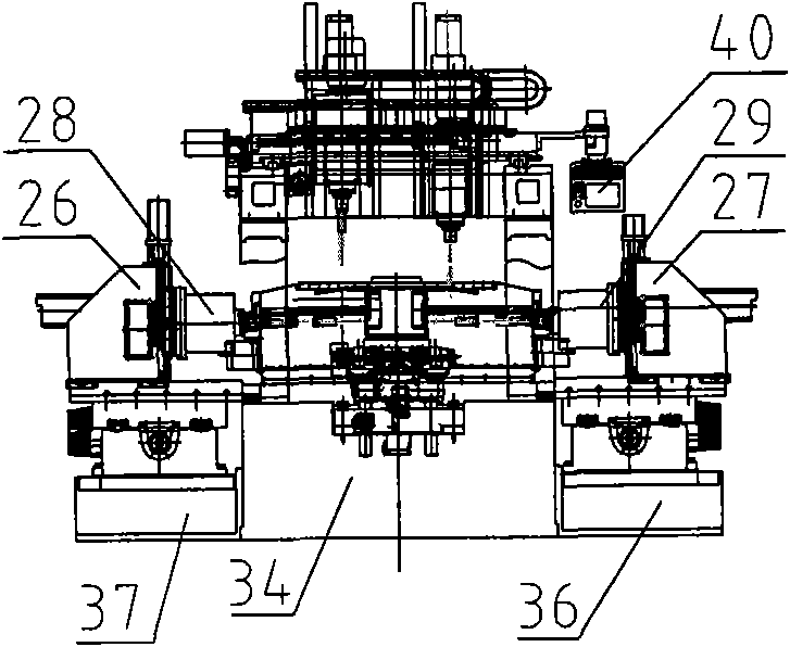
[0047] Such as Figure 1~5 As shown, the vertical ends of the machine tool of the present invention are arranged symmetrically at both ends. The present invention mainly includes the following structure: left gantry main body 1, right gantry main body 2, left vertical head CNC spindle box unit 3, right vertical head CNC spindle box unit 4, special-shaped Fixtures 5, 6, terminal fixtures 7, 8, chip boxes 9, 10, chip conveyors 11, 12, main fixtures 13, 14, auxiliary fixtures 15, 16, lateral guide wheels 17, 18, fine feed mechanisms 19, 20 , 21 is the feedway conveying mechanism composed of conveying rollers No. 1 to No. 11, which is used for the input and output of the center beam, and four sets of 80-specification Z-axis CNC slide tables 22 and 23 are used for processing 15 groups of holes and 12 on the side of the center beam. Horizontal coordinate position and rapid movement of the group hole system, four sets of horizontal X-axis CNC sliding tables 24, 25, used for drilling ...


PUM


Abstract

The invention discloses a numerical control center sill combined drilling machine, which comprises a gantry main body, a lathe bed, side bases, conveying sticks, a fixture, a chip cleaner and a chip collecting box. The technical key points are that: two longitudinal ends of the lathe bed are fully symmetrically arranged; two longitudinal sides of the two-end gantry main body are provided with the side bases; each of the side bases is provided with a three-dimensional numerical control sliding table which is provided with a single spindle box; a longitudinal center line of the two-end gantry main body is uniformly provided with at least two conveying sticks; and each of the conveying sticks is at least provided with a connecting motor. The numerical control center sill combined drilling machine has the advantages of simple mechanical structure, rational configuration of processing elements and power and mechanisms, convenient production operation and maintenance, coordinate variable control scheme, improvement of equipment production flexibility, creation of favorable conditions for future production of various products, improvement of the pollution on field working environment due to hydraulic systems and cooling systems, aerosol cooling and chip cleaning, improvement of the pollution on the working environment, multipoint positioning and clamping, and guarantee of the reliability and the stability of machining precision.

Description

technical field [0001] The invention relates to the technical field of machine tools, in particular to a drilling method mainly used for railway freight car C70, C64K, NX70, X6K, 6N70, 6Q70, ECH58, KM70, P64K, C80, NX80 type center beams and other special-shaped center beams CNC center beam combined drilling machine. Background technique [0002] As early as the 1970s, 1980s and 1990s, most of the vehicle manufacturers used six large radial drilling machines to complete the processing of the center beam. At least six employees are required to turn the center beam three times to complete the process. This process makes the labor intensity of workers very high, the accuracy is unstable, and the efficiency is also very low. It takes two hours to process a center beam. [0003] Later, at the beginning of this century, machine tool manufacturers developed a group drilling type center beam combined drilling machine for completing the processing of the center beam. Though this te...

Claims


Application Information

Patent Timeline
IPC IPC(8): B23B41/02B23B47/00B23B51/06B23Q7/00B23Q3/00B23Q11/10
Inventor 高树星王爱刚于凤兰
Owner SHENYANG XINGYE MACHINE TOOL
Learn More