
Biaxial rotation type locater

A dual-axis rotation and positioner technology, which is applied to large fixed members, auxiliary devices, program-controlled manipulators, etc., can solve problems such as increased dead zone, increased size R1, and collisions, and achieves the effect of improving the rotational driving ability

Inactive Publication Date: 2011-01-05
SUMITOMO HEAVY IND LTD
View PDF7 Cites 3 Cited by
  • Summary
  • Abstract
  • Description
  • Claims
  • Application Information

AI Technical Summary

Problems solved by technology

Therefore, if the second drive source 8 is arranged in parallel with the second rotation axis B, when the output torque of the second drive source 8 is to be increased, the second drive source 8 will inevitably become longer in the axial direction ( large), and there is a problem that the axial dead zone on the opposite side of the table surface of the workpiece table 13 becomes larger
In addition, since the axial size around the workpiece table 13 becomes very large, when the workpiece table 13 rotates around the first rotation axis A, the peripheral parts of the second drive source 8 collide with the main equipment such as an industrial robot or peripheral parts. danger
[0008] In the above-mentioned Patent Document 1, the second driving source 8 is arranged outside the radial direction of the second speed reducer 12 to avoid this problem, but as a result, not only the size of the work table radial direction near the second speed reducer 12 When R1 becomes larger and the second driving source 8 is further enlarged, the axial length L1 has to be increased accordingly.

Method used


Image

  • Biaxial rotation type locater
  • Biaxial rotation type locater
  • Biaxial rotation type locater

Examples


Embodiment Construction

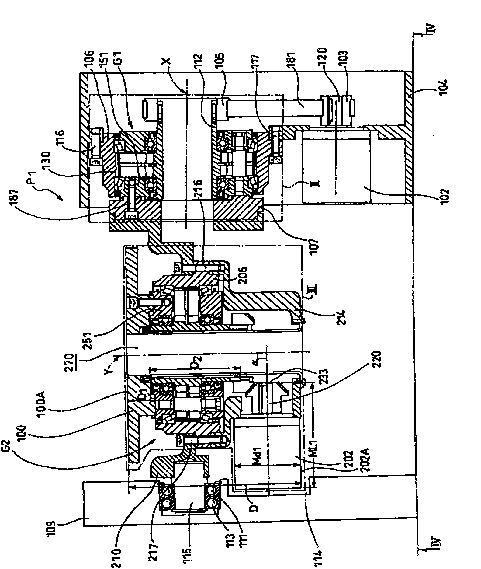
[0025] First, in order to clarify the application of the dual-axis rotary positioner P1, the industrial robot R1 will be explained for convenience. exist Figure 5 Represents a brief front view of the industrial manipulator R1, in Image 6 It shows a schematic side view of the industrial robot R1.

[0026] This industrial robot arm R1 has a base 20 on a floor 19 , and first to sixth joints 21 to 26 and first to sixth arms 28 to 33 are alternately connected to the base 20 . A drive motor and a speed reducer (both are not shown) are attached to the joints 21 to 26 . The first to sixth arms 28 to 33 are rotatable by receiving power from the drive motor and the speed reducer. The first to sixth arms 28 to 33 rotate around the axes of the first to sixth joints 21 to 26 .

[0027] Drive-controlled tools such as a welding mechanism, a gripping mechanism, and a coating mechanism are mounted on the front end of the sixth arm 33 .

[0028] With the above structure, the sixth arm 33...


PUM


Abstract

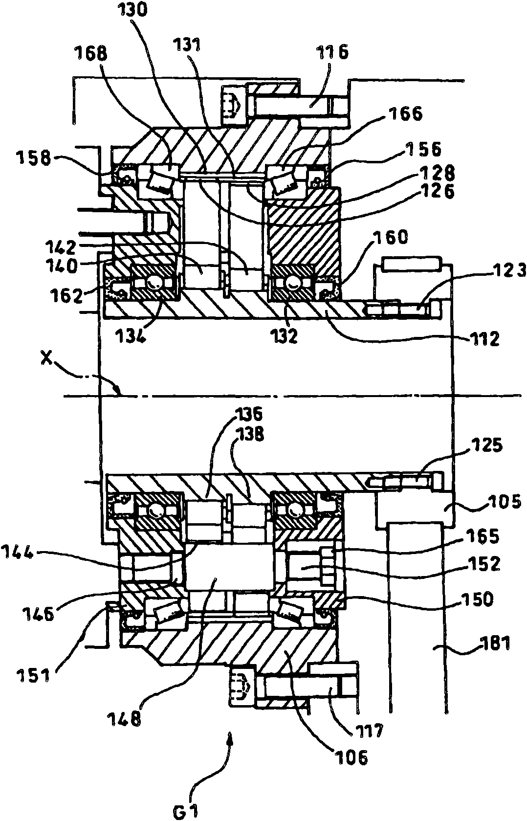
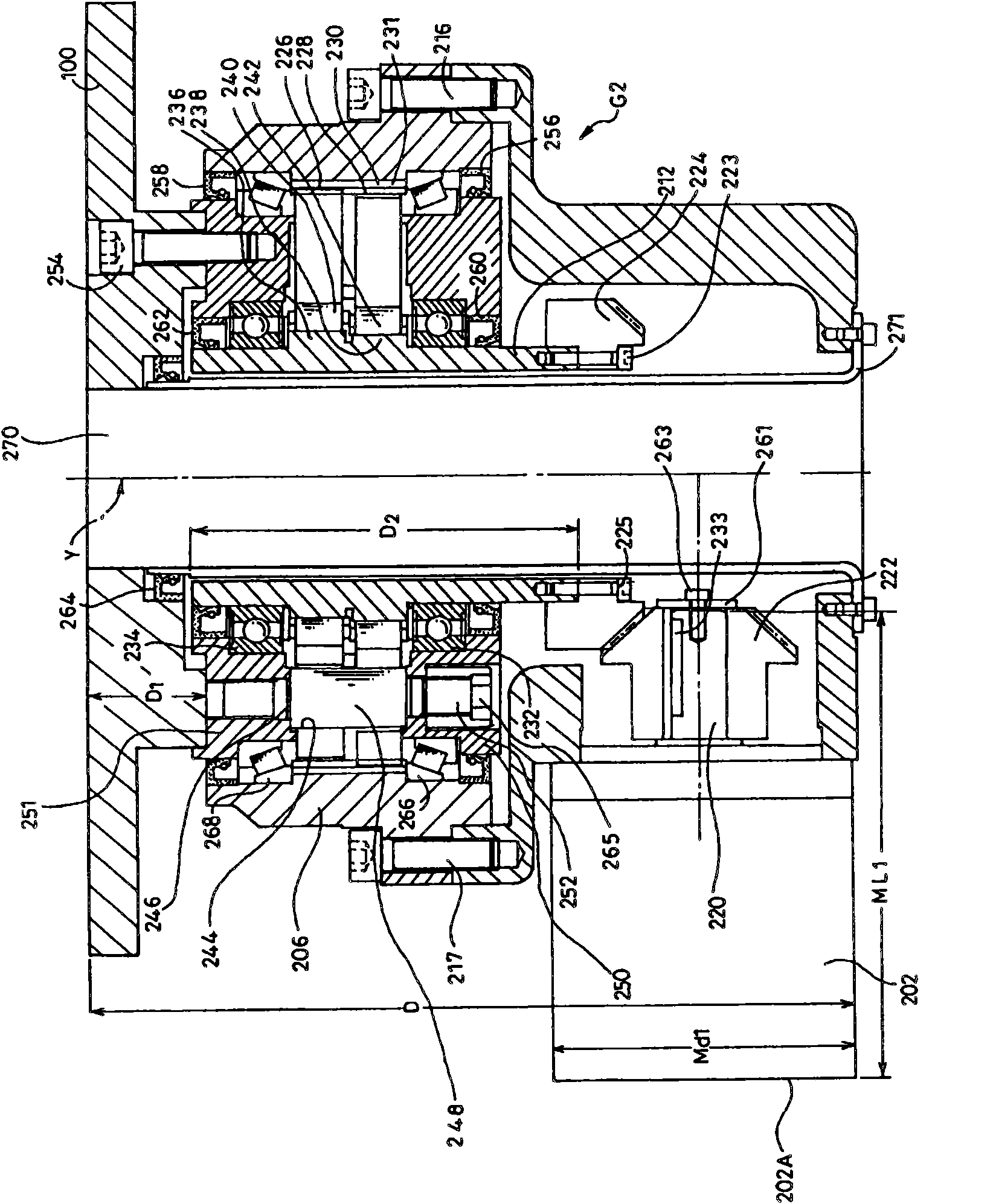
The present invention provides a biaxial rotation type locater, capable of trying for miniaturization of the locator regardless of the sizes of drive sources. The biaxial rotation type locater (P1) includes a workpiece table (100), a first drive source (102) and a second drive source (202), the rotation of the first drive source (102) is outputted from a first rotary member (151) with a horizontal first rotating axle (X), the rotation of the second drive source (202) is outputted from a second rotary member (251) with a second rotating axle (Y) which is vertical to a table board (100A) of the workpiece table (100), the workpiece table is connected to the first rotary member (151) and the second rotary member (152) so as to rotate around an axis that is parallel to the first rotating axis (X) and around the second rotating axis (Y), and an axis (220) of the second drive source (202) is orthogonal with the second rotating axis (Y).

Description

technical field [0001] This application claims priority based on Japanese Patent Application No. 2009-153685 filed on June 29, 2009. All the content of the application is used in this specification by reference. [0002] The invention relates to a dual-axis rotary positioner. Background technique [0003] In Patent Document 1, it is disclosed as Figure 7 Two-axis rotary positioner 1 shown. Figure 8 The periphery of the second reduction gear 12 is shown. [0004] The biaxial rotary positioner 1 includes a workpiece table 13 , a first drive source 3 , and a second drive source 8 . While outputting the rotation of the first driving source 3 from the first rotating member (output member of the first reducer 7 ) 6 having the first horizontal rotating shaft A, the second rotating shaft perpendicular to the table surface 13A of the workpiece table 13 is outputted. The second rotating member (output member of the second speed reducer 12 ) 11 of the shaft B outputs the rotation...

Claims


Application Information

Patent Timeline
IPC IPC(8): B23K37/047
CPCB23Q1/5437B25J9/0096
Inventor 石川哲三
Owner SUMITOMO HEAVY IND LTD
Learn More