Evaporative condensate pump circulating year-round refrigeration device

An evaporative condensation and evaporative condenser technology, applied in refrigerators, refrigeration components, refrigeration and liquefaction, etc., can solve the problems of reduced heat exchange efficiency, increased cost, increased space occupation, etc., to save manufacturing costs and equipment. Installation space, high heat exchange efficiency and cooling effect, effect of high heat exchange efficiency and cooling capacity

Active Publication Date: 2011-01-05
TSINGHUA UNIV +1
View PDF7 Cites 12 Cited by
  • Summary
  • Abstract
  • Description
  • Claims
  • Application Information

AI Technical Summary

Problems solved by technology

[0003] The traditional natural circulation of heat pipes has a good energy-saving effect, but there are two disadvantages: one is that it is necessary to provide system pipes and valves with larger diameters than summer refrigeration, which increases the cost and occupies more space; Insufficient refrigerant power and low circulation volume, etc., resulting in reduced heat transfer efficiency and limited cooling effect
[0004] In addition, the existing liquid supply method of the evaporator also has many shortcomings. The energy efficiency ratio of the dry system is low, and the liquid level control and oil return are difficult in the flooded system. Therefore, the market needs higher heat exchange efficiency and safety. Reliable evaporator liquid supply system improves the heat exchange efficiency of the evaporator

Method used


Image

  • Evaporative condensate pump circulating year-round refrigeration device
  • Evaporative condensate pump circulating year-round refrigeration device
  • Evaporative condensate pump circulating year-round refrigeration device

Examples


Embodiment 1

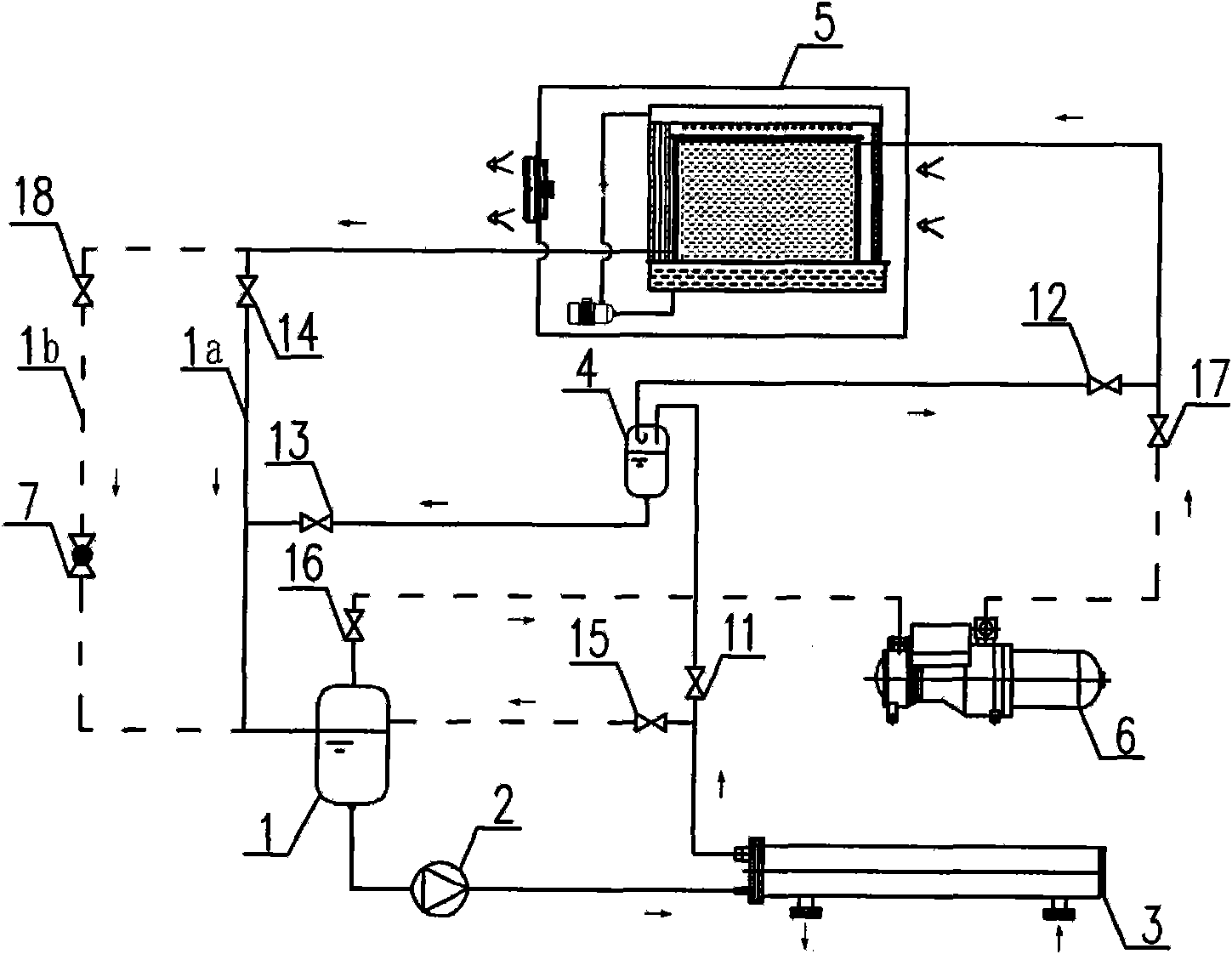
[0032] figure 1It shows a system schematic diagram of an evaporative condensate pump circulation year-round refrigeration device of the present invention, including a circulating liquid storage tank 1, a liquid pump 2, an evaporator 3, an evaporative condenser 5, a compressor 6, a throttling Device 7, the first low-pressure gas valve 15, the second low-pressure gas valve 16, the high-pressure gas valve 17, the fourth liquid pump refrigeration valve 14, the high-pressure liquid valve 18; The outlet of the bottom is connected, the outlet of the liquid pump 2 is connected with the inlet of the evaporator 3; The upper inlet is connected; the inlet of the second low-pressure gas valve 16 is connected with the upper outlet of the circulating liquid storage tank 1, and the outlet of the second low-pressure gas valve 16 is connected with the air inlet of the compressor 6; the high-pressure gas valve 17 The inlet is connected to the exhaust port of the compressor 6, and the outlet of ...

Embodiment 2

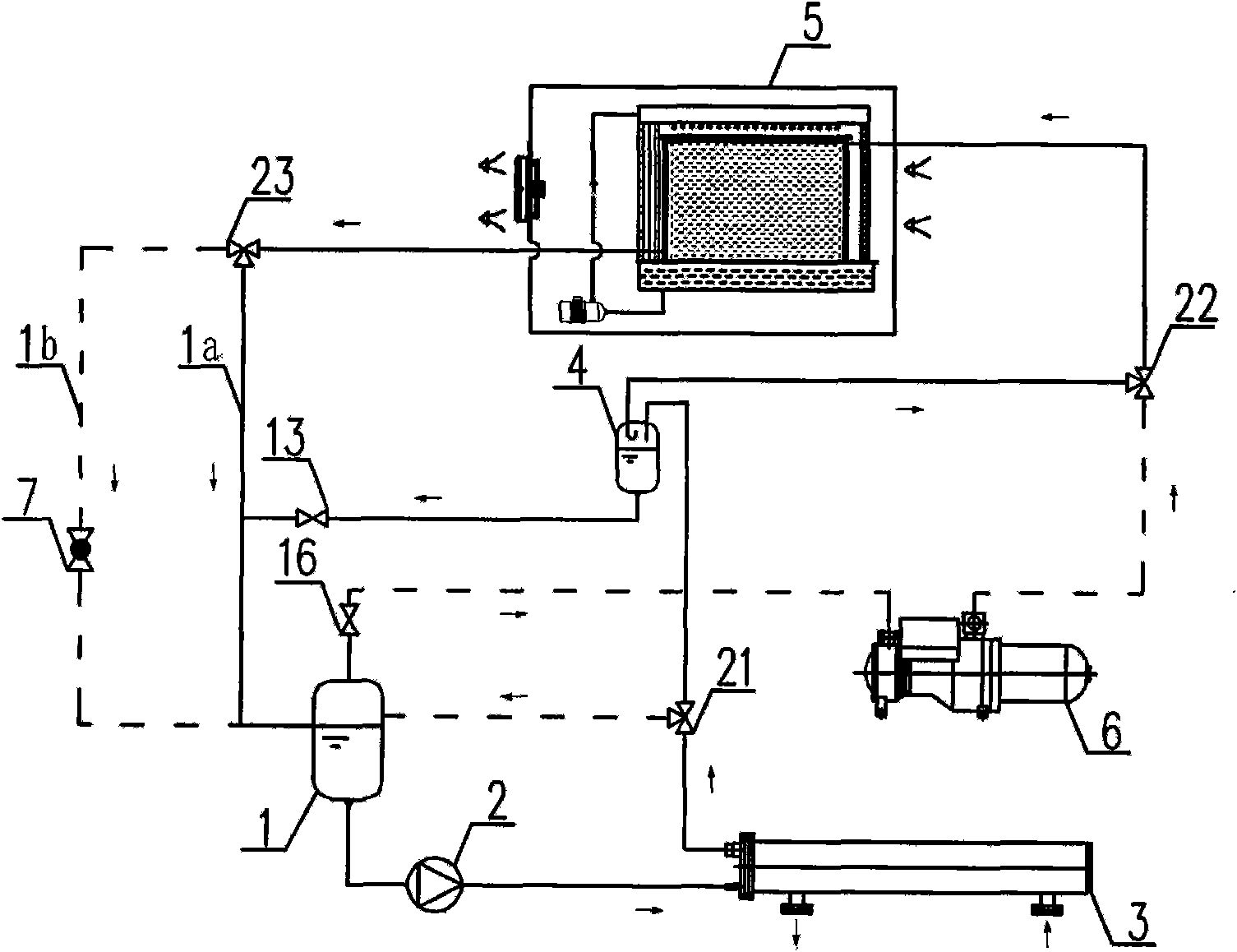
[0039] figure 2 A system schematic diagram of an evaporative condensate pump circulation year-round refrigeration plant using a three-way valve is shown. In this scheme, the first liquid pump refrigeration valve 11 and the first low-pressure gas valve 15 are combined into a first one-in two-out three-way valve 21; the second liquid pump refrigeration valve 12 and the high-pressure gas valve 17 are combined into a two-inlet One outlet three-way valve 22; the fourth liquid pump refrigeration valve 14 and the high-pressure liquid valve 18 are combined into a second one-in two-out three-way valve 23; the inlet of the first one-in two-out three-way valve 21 is connected to the evaporation The outlet of the device 3 is connected, and the two outlets of the first one-in-two-out three-way valve 21 are respectively connected with the upper inlet of the circulating liquid storage barrel 1 and the upper inlet of the gas-liquid separator 4; the two-in and one-out three-way valve 22 The ...


PUM


Abstract

The invention discloses an evaporative condensate pump circulating year-round refrigeration device, which comprises a liquid pump driven refrigeration cycle and a liquid supply steam compressed refrigeration cycle, wherein the liquid pump driven refrigeration cycle consists of a circulating liquid storage pump, a liquid pump, an evaporator, a first liquid pump refrigeration valve, a gas-liquid separator, a second liquid pump refrigeration valve, an evaporative condenser, a third liquid pump refrigeration valve and a fourth liquid pump refrigeration valve; the liquid supply steam compressed refrigeration cycle consists of a compressor, a high-pressure gas valve, an evaporative condenser, a high-pressure liquid valve, a throttling device, a circulating liquid storage barrel, a liquid pump, an evaporator, a first low-pressure gas valve and a second low-pressure gas valve; and the two cycles can be switched according to the use requirement, and a liquid refrigerant is conveyed to the evaporators by using the liquid pumps. Compared with the prior art, the evaporative condensate pump circulating year-round refrigeration device provided by the invention has the advantages of higher heat exchange efficiency, safe and reliable use and capability of efficiently and stably using outdoor natural cold quantity of winter and transition seasons.

Description

technical field [0001] The invention relates to a liquid pump circulation refrigeration device, in particular to an evaporative condensate pump circulation year-round refrigeration device suitable for year-round cooling spaces such as data machine rooms, computer centers and building inner areas. Background technique [0002] With the development of communication technology, the advent of the 3G network era and the rapid growth of Internet business demand, various high-density heating computer rooms, including IDC computer rooms, computer centers, server computer rooms, etc., are increasing day by day. Take the data computer room as an example. The electronic communication equipment inside the computer room generates large and concentrated heat. The heating intensity per square meter of the building can reach hundreds of watts or even thousands of watts, and it runs continuously throughout the year. Therefore, the computer room generally needs to be equipped with year-round c...

Claims


Application Information

Patent Timeline
Patent Type & Authority Applications(China)
IPC IPC(8): F25B25/00F25B41/04
CPCF25B13/00F25B41/04F25B2400/19F25B41/20F25B41/24
Inventor 石文星李志明周德海吴伟营何卫国
Owner TSINGHUA UNIV
Why Eureka
Try Eureka