Adaptive current detection circuit applied to wide-conversion ratio boost converter

A technology of current detection circuit and self-adaptive circuit, which is applied in the direction of measuring current/voltage, without intermediate conversion to AC conversion equipment, instruments, etc., which can solve the problem of increasing the number of off-chip components, compensating networks that cannot be integrated, and difficult system stability and good performance. Transient response and other issues, to achieve the effect of reducing cost, reducing the number of off-chip originals, and good application prospects

Inactive Publication Date: 2011-01-05
FUDAN UNIV
View PDF4 Cites 7 Cited by
  • Summary
  • Abstract
  • Description
  • Claims
  • Application Information

AI Technical Summary

Problems solved by technology

[0004] The BOOST type converter contains two poles and a zero point in the right half plane in the transfer function of its power stage, which makes the compensation network more complicated than the BUCK type under the traditional voltage control mode and current control mode, and it is difficult to operate in a wide Keep the system stable and good transient response under the conversion ratio
General products are implemented by selecting different compensation networks off-chip under different conversion ratios, making the compensation network unable to be integrated on-chip, increasing the number of off-chip components and increasing the cost
In addition, in the BOOST circuit, due to its discontinuous output current, the hysteresis control cannot be directly adopted

Method used


Image

  • Adaptive current detection circuit applied to wide-conversion ratio boost converter
  • Adaptive current detection circuit applied to wide-conversion ratio boost converter
  • Adaptive current detection circuit applied to wide-conversion ratio boost converter

Examples


Embodiment Construction

[0020] The present invention will be further described below in conjunction with the accompanying drawings.

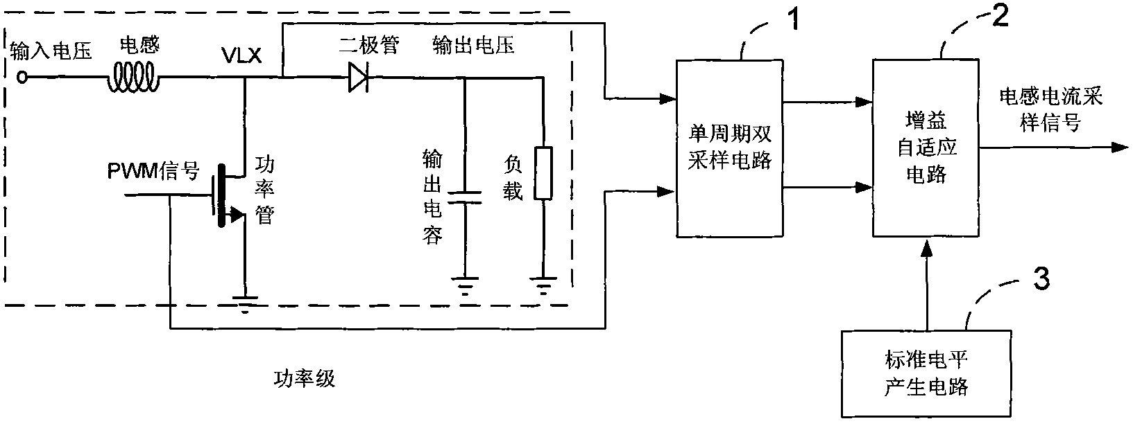
[0021] Such as figure 1 As shown, the block diagram of the adaptive current detection technology of the step-up DC-DC converter mentioned in the present invention, the circuit for realizing this technology includes: single-cycle double sampling circuit 1; reference level generation circuit 2; gain adaptive circuit 3.

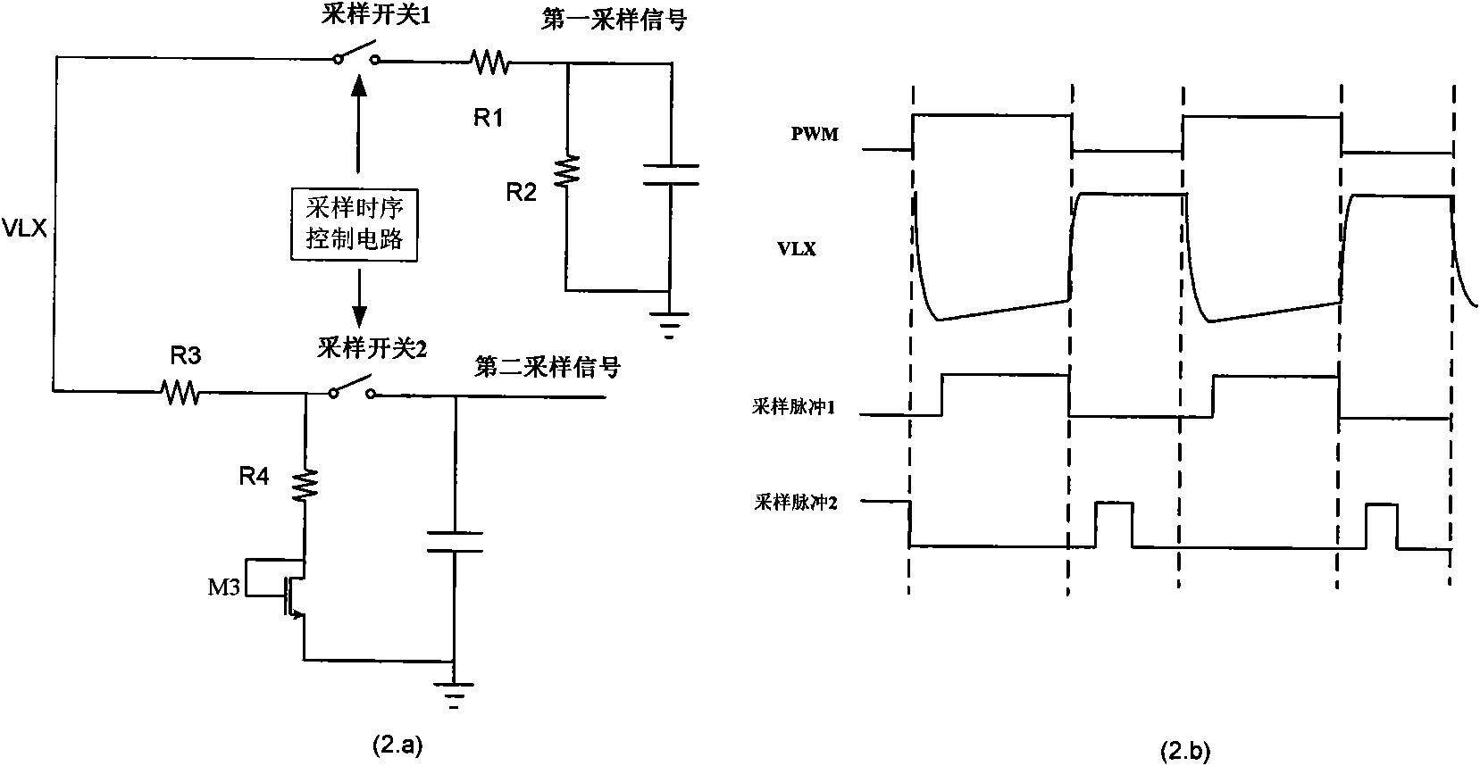
[0022] Such as figure 2 As shown, Figure (2.a) is a single-cycle double-sampling circuit diagram, and Figure (2.b) is a single-cycle double-sampling circuit diagram. Single-cycle double-sampling circuit 1 is used to generate two sampling signals: the inductor current signal and the output voltage signal , these two signals are provided to the gain adaptive circuit 3. It generates two sampling pulses according to the PWM control signal, and samples and processes the drain terminal voltage signal of the power tube respectively. When the power tube is ...


PUM


Abstract

The invention belongs to the technical field of integrated circuits, in particular to an adaptive current detection circuit applied to a wide-conversion ratio boost converter. The circuit comprises a single-period double-sampling circuit, a reference level generating circuit and an adaptive gain circuit, wherein the single-period double-sampling circuit is used for generating two sampling signals, namely an inductive current signal and an output voltage signal, and providing the signals for the self-adaptive gain circuit; the reference level generating circuit is used for generating a reference level and providing the reference level for the self-adaptive gain circuit; and the adaptive gain circuit generates a needed inductive current sampling signal which is adaptive to the output voltage by using the signals provided by the single-period double-sampling circuit and the reference level generating circuit. The adaptive current detection circuit avoids a method for implementing different conversion ratios by selecting an off-chip compensating network. Therefore, the adaptive current detection circuit has the advantages of making the compensating network become simple and integrated inside a chip, reducing the number of off-chip elements, meeting the requirement on portability, reducing the cost and having good application prospect.

Description

technical field [0001] The invention belongs to the technical field of integrated circuits, and in particular relates to a step-up DC-DC converter with a wide conversion ratio. Background technique [0002] DC-DC Converter (DC-DC Converter) is widely used in various electronic systems, especially the inductive-based DC-DC converter, due to its advantages of high efficiency and large output current capability, it is the most widely used. According to the relationship between the input voltage and the output voltage of the converter, it can be divided into buck type (BUCK), boost type (BOOST) and buck-boost type (BUCK-BOOST). The step-up converter is used to increase the power supply voltage to supply power to various circuit modules that require higher voltage power supply. For example, in the display screen of some handheld devices, 4 LED backlights connected in series need a voltage of about 12 volts, while the output voltage of a general battery is only 2.7V~5.5V. This r...

Claims


Application Information

Patent Timeline
Patent Type & Authority Applications(China)
IPC IPC(8): G01R19/00H02M3/02
Inventor 程林李叶倪金华洪志良
Owner FUDAN UNIV
Why Eureka
Try Eureka