Seismic scattering P-S converted wave imaging method

A technology of seismic scattering and imaging methods, applied in the direction of seismic signal processing, etc., which can solve the problems of inability to realize common conversion point gather selection and superposition imaging, difficult processing of seismic converted wave data, and inaccurate imaging results, etc., to achieve effective information The effect of fully utilizing, improving imaging accuracy, and increasing the number of stacking times

Inactive Publication Date: 2011-01-05
XI'AN PETROLEUM UNIVERSITY
View PDF3 Cites 1 Cited by
  • Summary
  • Abstract
  • Description
  • Claims
  • Application Information

AI Technical Summary

Problems solved by technology

[0002] Seismic converted wave data are difficult to deal with because the time-distance curves of reflected converted waves are neither symmetrical nor hyperbolic for common conversion points, and the traditional hyperbolic approximation is not applicable to converted waves at all.
The main problem comes from the sorting of common conversion point (CCP) gathers and the inherent characteristics of the time-distance relationship of converted waves. Even for a horizontal reflective layer in a homogeneous medium, the horizontal position of the converted reflection point of The depth of the layer and the change of the vertical and horizontal wave velocity ratio can not realize the real co-conversion point gather selection and stacking imaging. However, the laws of propagation of reflected waves and other components of seismic waves are different. If the seismic waves of other components are treated with reflection theory, the imaging results obtained must be inaccurate; at the same time, the Common Conversion Point (CCP) gather The processing technology is a set of processing technology developed for the horizontal layered homogeneous medium model. Strictly speaking, this technology is only suitable for horizontal layered uniform media, but in practice, this ideal situation is almost never
There are insurmountable deficiencies and difficulties in the theoretical and practical application of traditional seismic imaging technology. Therefore, other processing technologies must be sought to improve or solve the problem of defects in the imaging effect of current seismic imaging technology, especially in areas with complex underground structures ( Such as piedmont fault zone, basin edge broken zone, frequent geological structure activity zone, etc.), heterogeneous prominent zone, geological structure is far from the horizontal layered uniform medium model (such as magmatic intrusion, metamorphic body, lens body, limestone karst caves, metal veins, etc.) and severely weathered areas near the surface, etc.

Method used


Image

  • Seismic scattering P-S converted wave imaging method
  • Seismic scattering P-S converted wave imaging method
  • Seismic scattering P-S converted wave imaging method

Examples


Embodiment 1

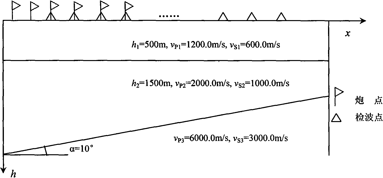
[0048] Taking a two-component inclined stratigraphic model seismic data with 60 shots, 24 traces per shot, and 1500 sampling points per trace as an example to illustrate the implementation steps of this example:

[0049] Step 1: Read the seismic data containing 51 shots, 64 traces per shot, and 1024 sampling points per trace into a two-dimensional array F 1 , F 2 At the same time, the parameters of the observation system are loaded into the trace head of the original seismic data, and the positions and coordinates of the scattering points are calculated according to the observation system and acquisition parameters;

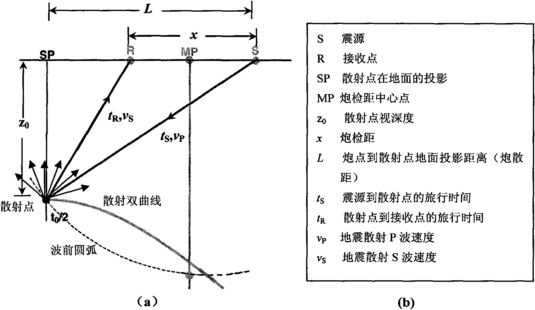
[0050] Step 2: According to the time-distance hyperbolic equation of the scattered wave, on the shot set, fix t 0i In the case of the imaging velocity (including the P-wave velocity v P and shear wave velocity v S ) to determine the scatter P-SV and P-P wave hyperbolic trajectories respectively, and then calculate the seismic scatter P-SV and P-P wave normal t...

Embodiment 2

[0070] Take a three-component actual seismic survey data containing 146 shots, 86 traces per shot, and 2000 sampling points per trace as an example to illustrate the implementation steps of this example:

[0071] Step 1: read the three-component seismic data containing 146 shots, 86 traces per shot, and 2000 sampling points per trace into the two-dimensional array F 1 , F 2 , F 3 At the same time, the parameters of the observation system are loaded into the original seismic data track head respectively, and the positions and coordinates of the scattering points are calculated according to the observation system and acquisition parameters;

[0072] Step 2: According to the time-distance hyperbolic equation of the scattered wave, on the shot set, fix t 0i In the case of the imaging velocity (including the P-wave velocity v P and shear wave velocity v S ) to determine the seismic scatter P-SV, P-SH and P-P wave hyperbolic trajectories respectively, and then calculate the seis...


PUM


Abstract

The invention discloses a seismic scattering converted wave imaging method, comprising the following steps: step 1. reading the seismic data into a two-dimensional array F, loading an observing system parameter to an original seismic data trace header, and calculating the position and the coordinate of a scattering point according to the observing system and the acquired parameters; step 2. determining a scattering hyperbolic trace in an imaging speed under the condition of fixing t0i according to a scattered wave time-distance hyperbolic equation, and then calculating the normal time difference of the seismic scattering P-S converted wave; step 3. subtracting the normal time difference of the seismic scattering P-S converted wave when the seismic wave travels; step 4. weighting and summing the scattering amplitudes of the hyperbolic traces subtracting the normal time difference of the seismic scattering P-S converted wave on each geophone offset, so as to realize seismic scattering P-S converted wave imaging; and step 5. outputting the imaging result according to a data format. The superposing times with a horizontally superposing imaging technique are greatly increased, the signal to noise ratio can be effectively improved, the imaging precision can be effectively improved, and the acquired geological information is richer.

Description

technical field [0001] The invention belongs to the technical field of seismic wave imaging processing, in particular to a seismic scattering P-S converted wave imaging method. technical background [0002] Seismic converted wave data are difficult to deal with because the time-distance curves of reflected converted waves are neither symmetrical nor hyperbolic to common conversion points, and the traditional hyperbolic approximation is not applicable to converted waves at all. The main problem comes from the sorting of common conversion point (CCP) gathers and the inherent characteristics of the time-distance relationship of converted waves. Even for a horizontal reflective layer in a homogeneous medium, the horizontal position of the converted reflection point of The depth of the layer and the change of the vertical and horizontal wave velocity ratio can not realize the real co-conversion point gather selection and stacking imaging. However, the laws of propagation of refl...

Claims


Application Information

Patent Timeline
Patent Type & Authority Applications(China)
IPC IPC(8): G01V1/28G01V1/30
Inventor 沈鸿雁
Owner XI'AN PETROLEUM UNIVERSITY
Why Eureka
Try Eureka