

High voltage filter and dynamic reactive power compensation control system combining PPF with TSC and control method thereof
A compensation control and dynamic compensation technology, applied in reactive power compensation, reactive power adjustment/elimination/compensation, harmonic reduction devices, etc. The effect of grid terminal voltage and improving reactive power compensation capacity
- Summary
- Abstract
- Description
- Claims
- Application Information
AI Technical Summary
Problems solved by technology
Method used
Image

Examples
specific Embodiment approach 1
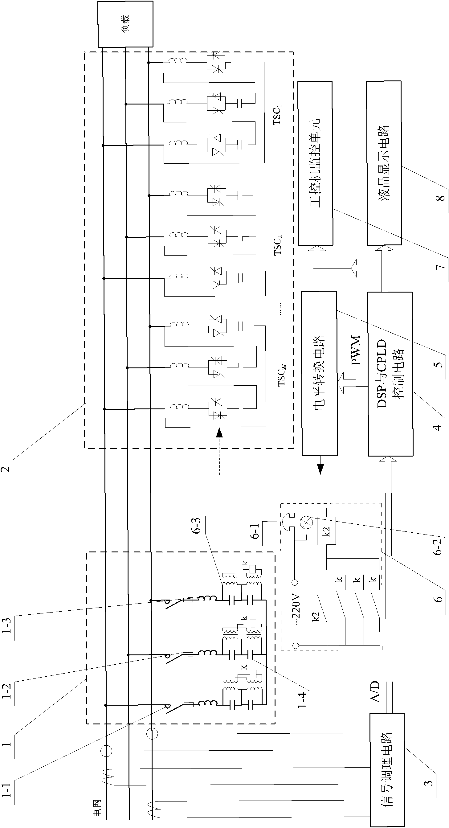
[0026] Specific implementation mode one: the following combination Figure 1 to Figure 2 Describe this embodiment, the high-voltage filtering and dynamic reactive power compensation control system combining PPF and TSC described in this embodiment includes a passive filter unit 1, a reactive power dynamic compensation unit 2, a signal conditioning circuit 3, and a DSP and CPLD control circuit 4 and level shifting circuit 5,
[0027] The passive filtering unit 1 and the reactive power dynamic compensation unit 2 are connected in parallel between the grid input terminal and the load terminal, and the signal conditioning circuit 3 is used to detect the three-phase current signal and the three-phase voltage signal at the input terminal of the grid, and the voltage of the signal conditioning circuit 3 The voltage and current signal input terminals of the DSP and the CPLD control circuit 4 are connected to the current signal output terminal, the PWM control signal output terminal of...
specific Embodiment approach 2
[0028] Specific implementation mode two: the following combination figure 2 Describe this embodiment. This embodiment is a further description of Embodiment 1. The passive filter unit 1 is composed of three star branches, and the three star branches are connected in star form. Each star branch is routed by a circuit breaker 1 -1, fuse 1-2, filter reactor 1-3 and two filter capacitors 1-4,
[0029] A circuit breaker 1-1, a fuse 1-2, a filter reactor 1-3 and two filter capacitors 1-4 in each star branch are connected in series in sequence. Other components and connections are the same as those in Embodiment 1.
specific Embodiment approach 3
[0030] Specific implementation mode three: the following combination figure 2 This embodiment is described. This embodiment is a further description of Embodiment 1. The reactive power dynamic compensation unit 2 is composed of M groups of thyristor switching capacitors TSC, and the compensation capacity of M groups of thyristor switching capacitors TSC is according to 2 n-1 Coding method grouping, n=1, 2, ..., N, where M is an integer greater than 1, N≤M, M groups of thyristor switching capacitors TSC are connected to the power grid in parallel,
[0031] Each group of thyristor switching capacitors TSC is composed of three angular branches connected in an angular shape, and each angular branch is composed of an inductance coil, two anti-parallel thyristors and capacitors in series. Other components and connections are the same as those in Embodiment 1.
PUM
 Abstract
Description
Claims
Application Information