

Rate de-matching method and device for finite length circular buffering rate matching
A solution rate matching and circular buffering technology, which is applied in the field of solution rate matching for limited-length circular buffer rate matching, can solve the problems of long solution rate matching process and low solution rate matching throughput, so as to shorten time and improve throughput volume effect
- Summary
- Abstract
- Description
- Claims
- Application Information
AI Technical Summary
Problems solved by technology
Method used
Image

Examples
no. 1 example
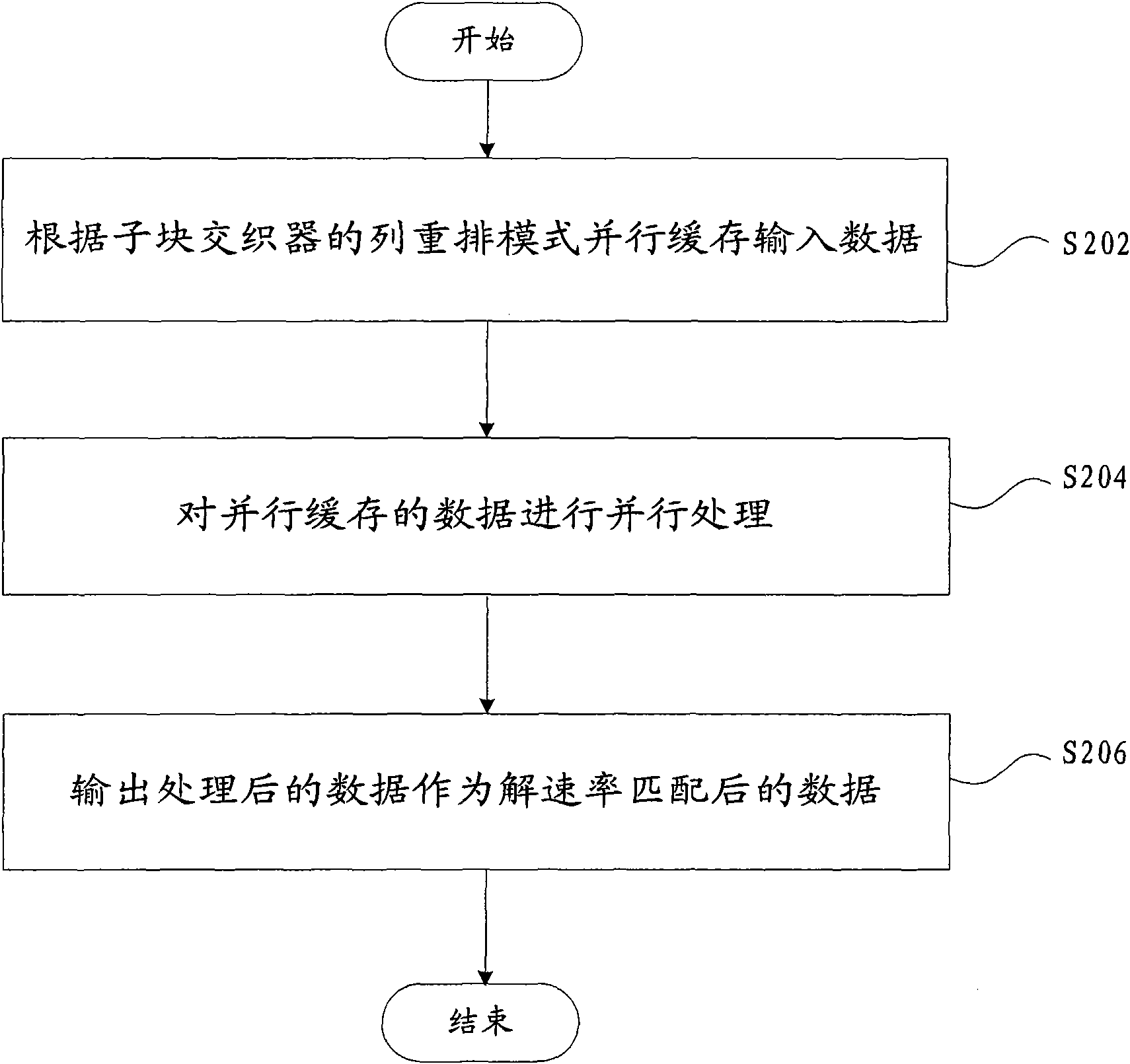
[0032] figure 2 It is a flow chart of the method for de-rate matching of limited-length circular buffer rate matching according to the first embodiment of the present invention. like figure 2 As shown, according to the first embodiment of the present invention, the solution rate matching method of limited-length circular buffer rate matching includes the following steps:
[0033] Step S202, buffering the input data in parallel according to the column rearrangement mode of the sub-block interleaver;
[0034] Step S204, performing parallel processing on the data cached in parallel;
[0035] Step S206, outputting the processed data as data after de-rate matching.
[0036] In step S202, there are two reasons for data caching: 1. The punching pattern is not known when the solution rate matching is started, so the data needs to be cached first, and wait for the punching pattern to be calculated; 2. When the data is subsequently processed, NULL needs to be added to the data. If...
no. 2 example
[0047] Figure 5 It is a block diagram of a de-rate-matching device for rate-matching a finite-length circular buffer according to the second embodiment of the present invention. like Figure 5 As shown, the de-rate-matching device for finite-length circular buffer rate-matching according to the second embodiment of the present invention includes: a buffering module 502 for buffering input data in parallel according to the column rearrangement mode of a sub-block interleaver; a processing module 504 for It is used to perform parallel processing on the data in the parallel cache; the output module 506 is used to output the processed data as the data after de-rate matching.
[0048] According to the second embodiment of the present invention, the limited-length circular cache rate matching de-rate matching device caches the input data in parallel according to the column rearrangement mode of the sub-block interleaver, and performs parallel processing on the cached data, thereby...
no. 3 example
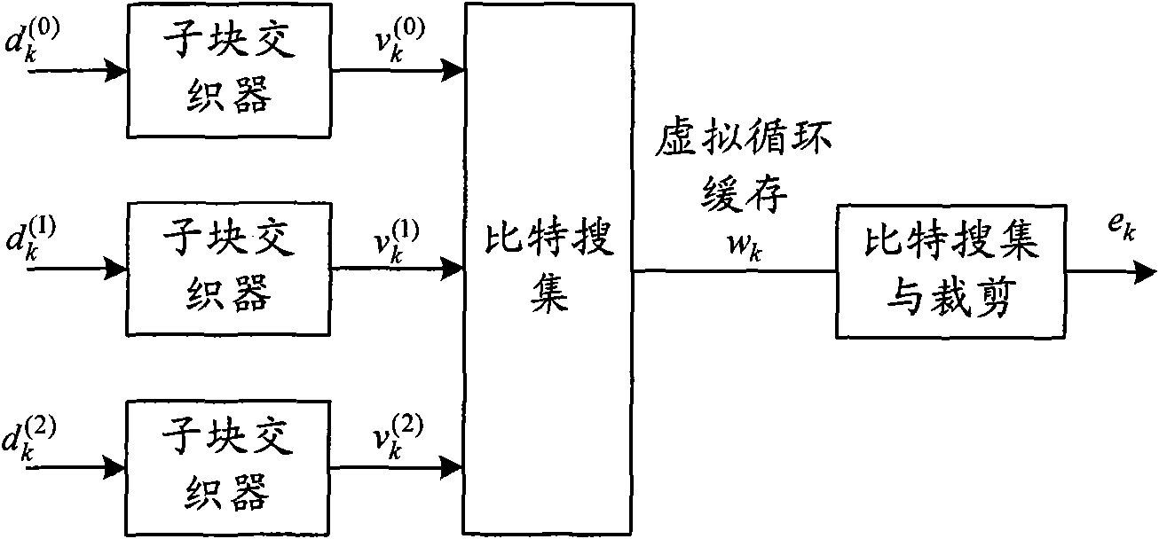
[0056] Image 6 It is an overall block diagram of a rate-matching de-matching device for a limited-length circular buffer rate-matching according to the third embodiment of the present invention.
[0057] like Image 6 As shown, in the rate-matching de-matching apparatus for limited-length circular buffer rate matching according to the third embodiment of the present invention, the MEM 602 implements parallel buffering of input data. In this embodiment, the data is 4-way parallel buffering. In addition, assume that the column rearrangement pattern of the sub-block interleaver is as follows:
[0058]
[0059] Analyzing the interleaved column rearrangement mode, it can be found that the above interleaved columns can be divided into four groups: 0, 16, 8, 24, 4, 20, 12, 28; 2, 18, 10, 26, 6, 22, 14, 30; ;1,17,9,25,5,21,13,29;3,19,11,27,7,23,15,31. Therefore, four RAMs can be used to store each channel, the first RAM stores information in columns 0, 16, 8, 24, 4, 20, 12, and...
PUM
 Abstract
Description
Claims
Application Information