
Carrying apparatus and hot-rolling apparatus, and carrying method and hot-rolling method

A conveying device and conveying roller technology, applied in forging and pressing devices, workpiece heating devices, furnace control devices, etc., can solve the problems of conveying roller impact, bending or warping of workpieces, etc. Effect

Inactive Publication Date: 2011-01-05
IHI CORP
View PDF2 Cites 9 Cited by
  • Summary
  • Abstract
  • Description
  • Claims
  • Application Information

AI Technical Summary

Problems solved by technology

[0006] However, since the workpiece (especially the front end) after rough rolling is easily deformed such as bending or warping, the conveying rollers in the heating and holding furnace receive impact from the workpiece

Method used


Image

  • Carrying apparatus and hot-rolling apparatus, and carrying method and hot-rolling method
  • Carrying apparatus and hot-rolling apparatus, and carrying method and hot-rolling method
  • Carrying apparatus and hot-rolling apparatus, and carrying method and hot-rolling method

Examples


Embodiment Construction

[0051] Hereinafter, an embodiment of the present invention will be described with reference to the drawings.

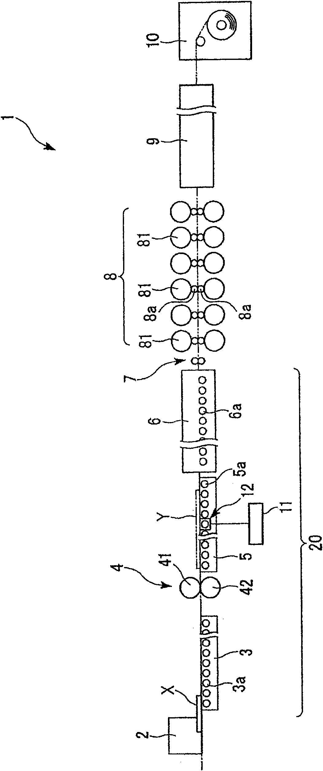
[0052] figure 1 It is a figure which shows the schematic structure and functional structure of the conveying apparatus 20 which is one embodiment of this invention, and the hot rolling apparatus 1 provided with this conveying apparatus 20.

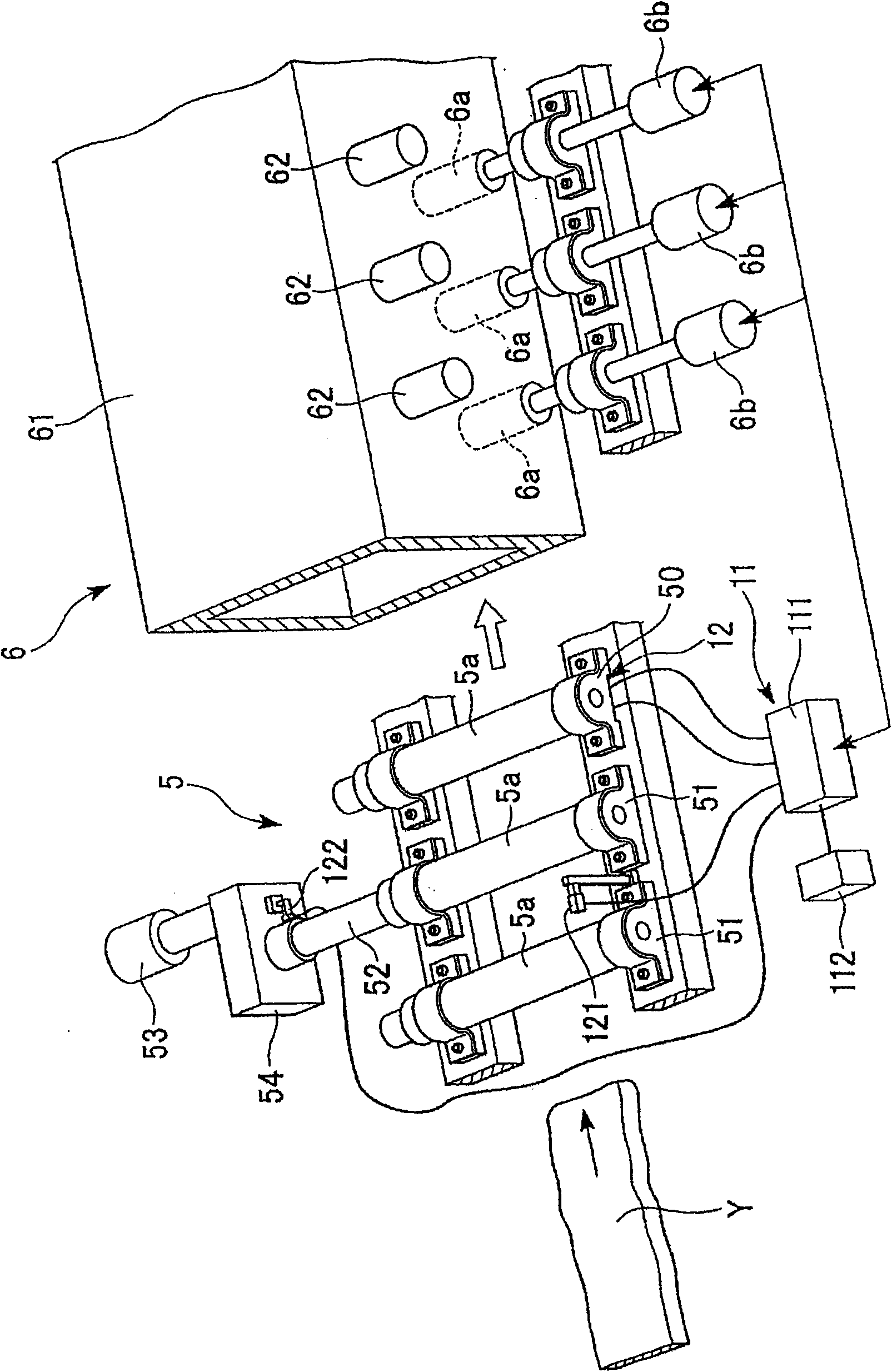
[0053] As shown in the figure, the hot rolling apparatus 1 of this embodiment includes a heating furnace 2, a front roller table 3, a rough rolling mill 4, a rear roller table 5, a heating and holding furnace 6, a shearer 7, a finishing mill 8, and a cooling device 9. , a winding machine 10, a control unit 11, and a data acquisition unit 12 for impact prediction.

[0054] The heating furnace 2 heats a slab X (workpiece) containing copper and mainly composed of steel to a temperature suitable for the rough rolling process before rolling by the rough rolling mill 4 .

[0055] The front roller table 3 is arranged in the rear stage ...


PUM


Abstract

Disclosed is a carrying apparatus, which comprises a plurality of carrying rollers supported in parallel at a predetermined spacing, so that a workpiece is carried from a rolling machine to the inside of a heat keeping-applying furnace by the carrying rollers. The carrying apparatus is characterized by further comprising a shock-predicting data collection unit for acquiring such data upstream of the heat keeping-applying furnace as to predict the magnitude of shocks to be applied by the workpiece to that one of the carrying rollers, which is disposed in the heat keeping-applying furnace, and a control unit for predicting the magnitude of the shocks from that data acquired by the shock-predicting data collection unit, thereby to adjust the carrying speed of carrying the workpiece in the heat keeping-applying furnace in accordance with the magnitude of the shocks.

Description

technical field [0001] The invention relates to a conveying device and a hot rolling device as well as a conveying method and a hot rolling method. [0002] This application claims priority based on Patent Application No. 2008-008136 for which it applied in Japan on January 17, 2008, and takes in the content here. Background technique [0003] Conventionally, a hot rolling apparatus for hot rolling a workpiece such as a steel plate includes a roughing mill and a finishing mill, a heating furnace or a heating and holding furnace, a shear, a coiler, and the like. [0004] In the above-mentioned hot rolling device, firstly, the workpiece is heated by the heating furnace, and then the workpiece is rough-rolled by the rough rolling mill, and the workpiece is reheated and kept warm in the heating and holding furnace, and transported at the same time, and passed through the shearing machine. The front end and end of the workpiece are cut off, the workpiece is finished rolled by th...

Claims


Application Information

Patent Timeline
Patent Type & Authority Applications(China)
IPC IPC(8): B21B39/00B21B1/26B21B45/00B21C51/00
CPCB21B39/00F27B9/40F27D3/026F27D21/02F27B9/2407B21C51/00B21B45/004B21B15/005F27D19/00
Inventor 口诚宽石井肇本城恒
Owner IHI CORP
Learn More