Brake system

A brake system and brake technology, which is applied in the direction of brakes, etc., can solve the problems of increasing the air consumption of the auxiliary accumulator, increasing the air consumption, and increasing the air consumption of the braking system, so as to reduce the total air consumption and reduce the Inflation time, effect of reducing brake release time

Active Publication Date: 2011-01-05
KNORR BREMSE RAIL SYST UK LTD
View PDF7 Cites 8 Cited by
  • Summary
  • Abstract
  • Description
  • Claims
  • Application Information

AI Technical Summary

Problems solved by technology

[0004] Wheel slip protection increases the air consumption of the braking system, typically four to ten times the air consumption of the same system without wheel slip protection
Especially in monotube brake systems this causes the problem that the size of the auxiliary accumulator needs to be increased by a similar amount to the increase in air consumption

Method used


Image

  • Brake system
  • Brake system
  • Brake system

Examples


Embodiment Construction

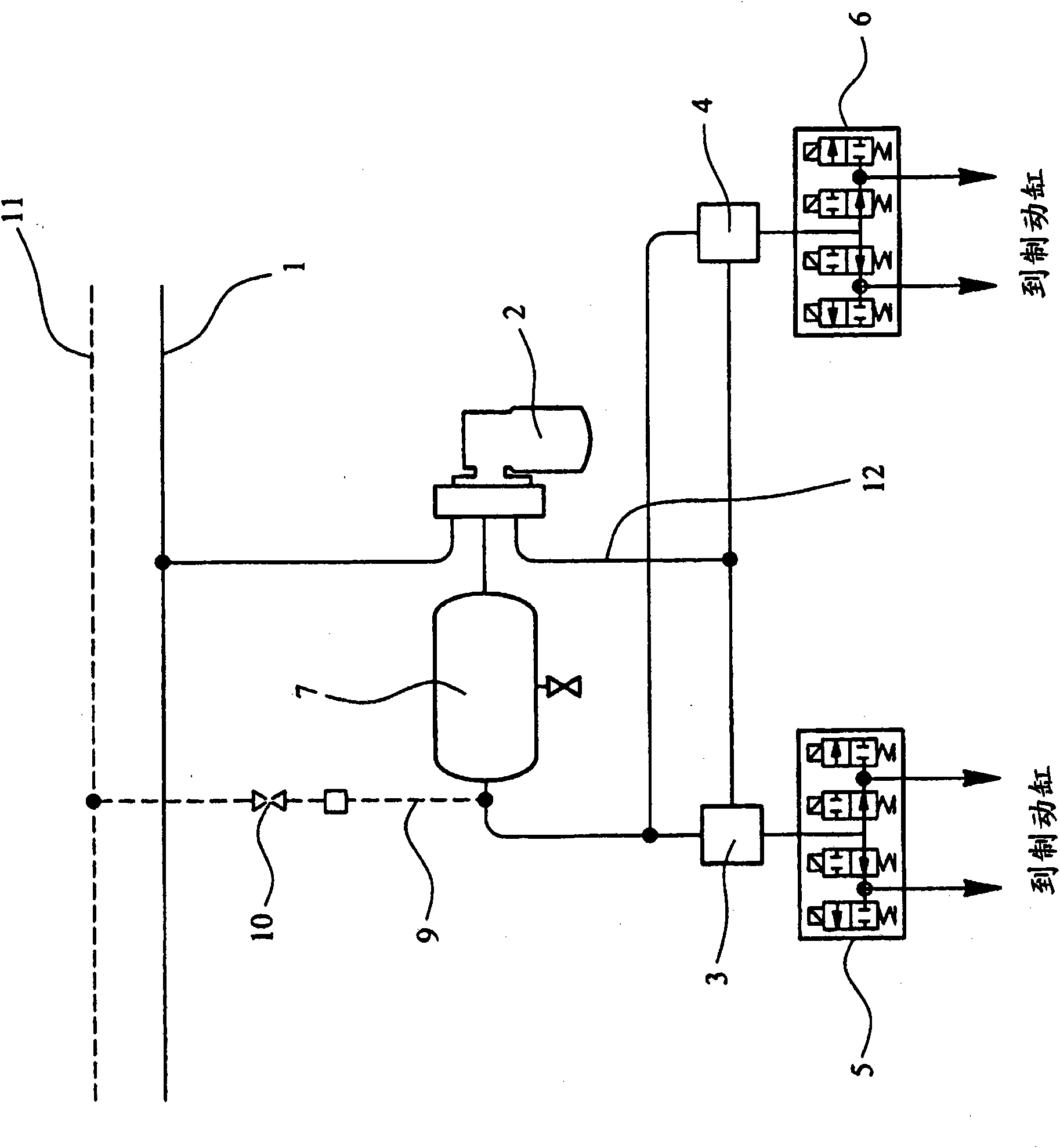
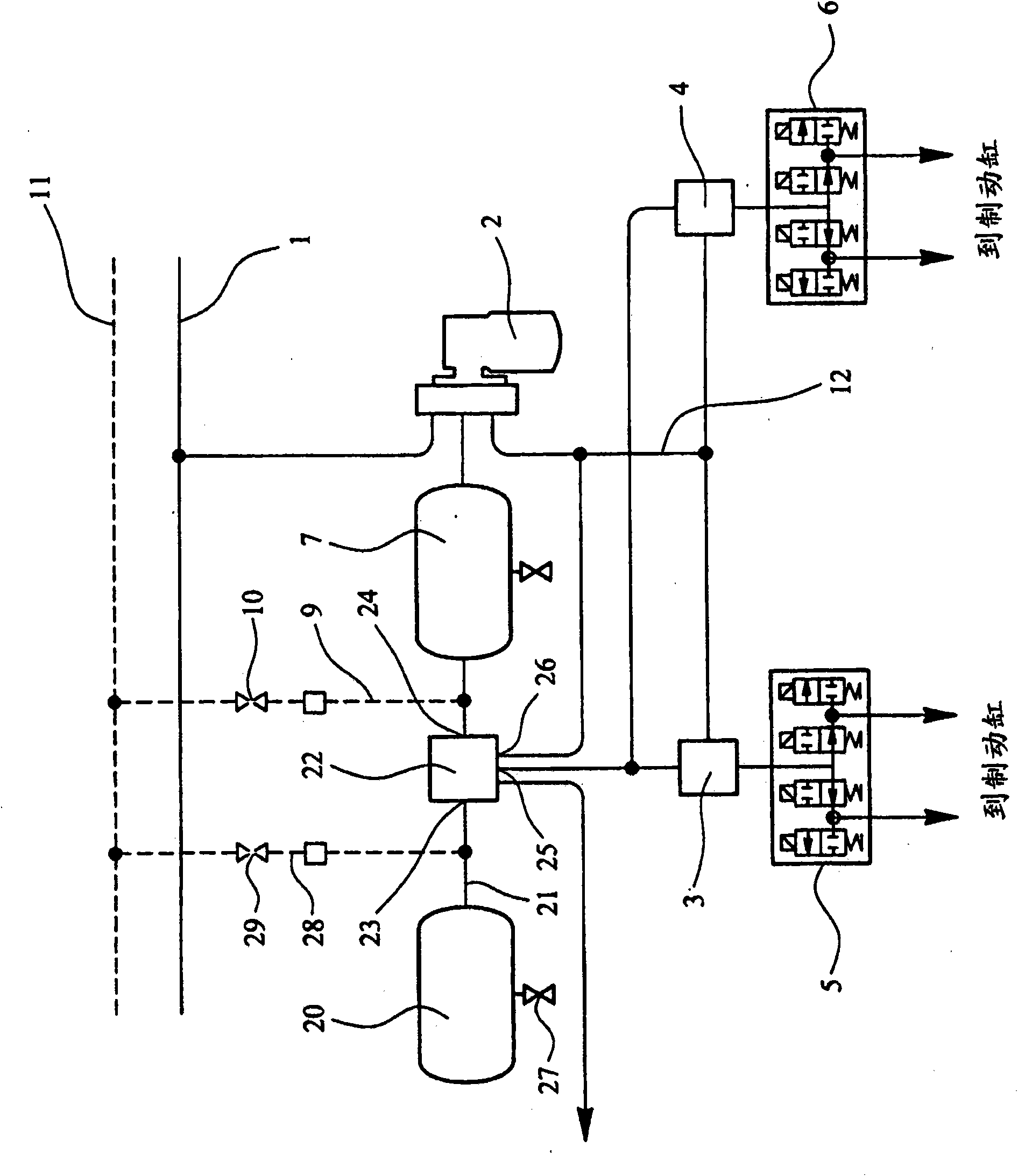
[0022] figure 1 A schematic diagram showing a part of a known arrangement for a rail brake system comprising a main brake pipe 1 in fluid communication with a brake distributor 2 which is fluidly connected via a line 12 to relay valves 3, 4 which are each connected to a respective relief valve 5, 6 which is connected to a respective brake cylinder (not shown ). The brake distributor 2 has virtual cylinder pressure and will usually have integrated relay valve capability. Typically, there will be one relay valve and one dump valve per bogie, or one dump valve per axle. It is also known to use variable load valves instead of the relay valves 3 , 4 .

[0023] An auxiliary accumulator 7 is provided which remains in fluid communication with the brake distributor 2 via a first outlet and is also in fluid communication with each of the relay valves 3 , 4 via a second outlet. The auxiliary accumulator pressure is protected by a check valve in distributor 2. The solid lines show th...


PUM


Abstract

A brake system for a railway vehicle having wheel slide protection comprises a main brake pipe (1) fmidly connected to a distributor (2), and an auxiliary reservoir (7) fluidly connected to the brake distributor (2), the distributor (2) being fluidly connected to one or more brake cylinders (3, 4). A further reservoir (20) is provided, compressed air flow to and from the further reservoir (20) being controllable by a valve (22), operation of the valve being controlled by a control unit adapted to detect wheel slide. The control unit is adapted to switch air supply between air from the auxiliary reservoir (7) and air from the further reservoir (22) in the event that wheel slide is detected.

Description

technical field [0001] The invention relates to a braking system for a rail vehicle including wheel slide protection. Background technique [0002] Rail vehicle braking systems are typically air brakes and may be either single or dual line systems. In recent years, such systems including wheel slip control and wheel spin control have been established. Both wheel slip and wheel spin result from low adhesion of the wheels to the track. Wheel slip typically occurs when braking a rail vehicle, and wheel slip occurs when the vehicle is accelerating. [0003] A typical wheel slip control system includes a plurality of sensors on each axle of the vehicle, the sensors being adapted to measure the rotational speed of the axle. The sensors are respectively connected back to a central vehicle brake control unit through wiring harnesses. In use, the output of the sensor is fed to the brake control unit which compares this value with that of the adjacent axle and, if the difference e...

Claims


Application Information

Patent Timeline
Patent Type & Authority Applications(China)
IPC IPC(8): B60T8/32
CPCB60T8/3235B60T8/3245B60T13/665
Inventor R·布拉德利A·托马斯M·亨明斯
Owner KNORR BREMSE RAIL SYST UK LTD
Why Eureka
Try Eureka