Installation of diesel engine camshaft and lubrication structure

A lubricating structure and camshaft technology, applied in the direction of engine lubrication, camshaft drive, valve accessories lubrication, etc., can solve the problems of complex oil circuit and insufficient lubricating oil in bearing parts, and achieve stable operation, sufficient lubrication, and simplified installation structure effect

Active Publication Date: 2011-01-12
WUXI KIPOR POWER CO LTD
View PDF5 Cites 8 Cited by
  • Summary
  • Abstract
  • Description
  • Claims
  • Application Information

AI Technical Summary

Problems solved by technology

[0002] In the traditional technology, a bearing support installation structure is provided on the structure supporting the camshaft formed between the body of the engine and the crankcase. In order to deliver lubricating oil to the camshaft support journal and bearing part, usually by setting an internal oil passage or Pipes and other forms are connected to the shaft groove and the oil injection port of the oil pump, and the high-pressure lubricating oil is delivered from the oil pump to the shaft groove to form a lubrication structure between the shaft and the bearing. The oil circuit is complicated, and some oil mist lubrication is also used, but It is easy to cause the problem of insufficient lubricating oil in the bearing part

Method used


Image

  • Installation of diesel engine camshaft and lubrication structure
  • Installation of diesel engine camshaft and lubrication structure
  • Installation of diesel engine camshaft and lubrication structure

Examples


Embodiment Construction

[0019] Below the present invention will be further described in conjunction with the embodiment in the accompanying drawing:

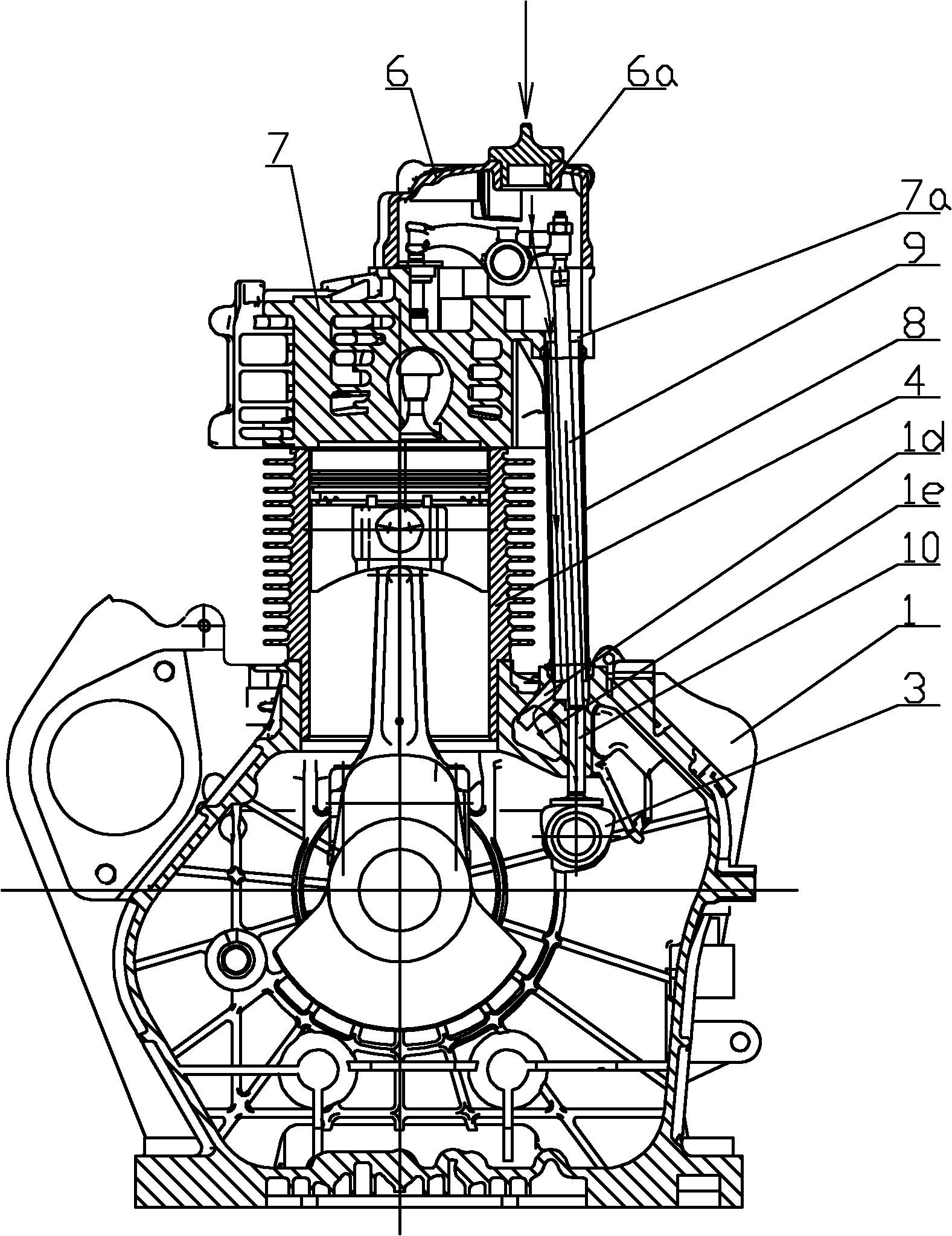
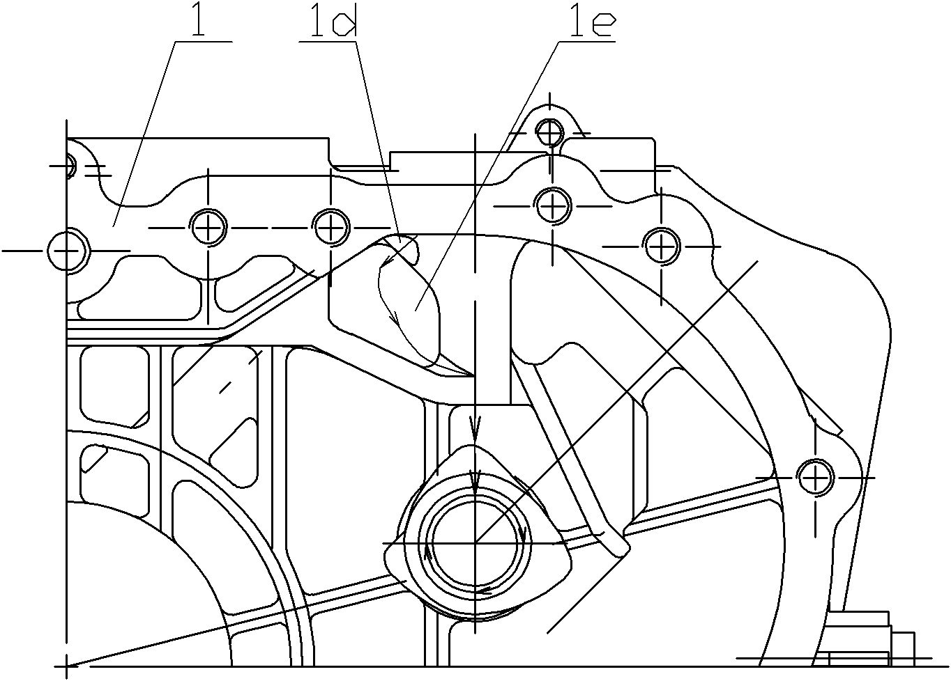
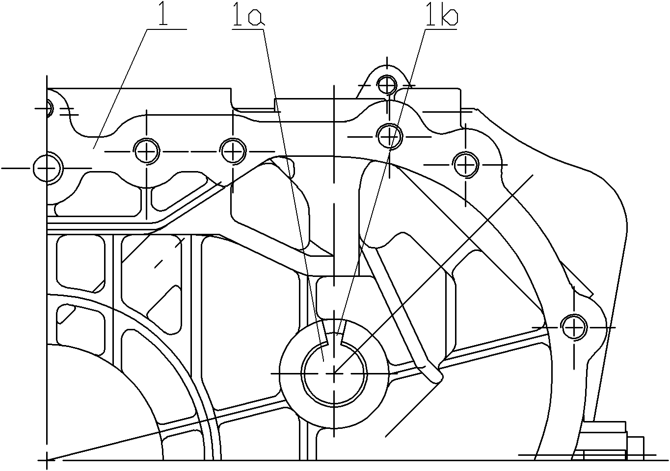
[0020] Such as Figure 1 to Figure 5 As shown, the present invention mainly consists of body 1 (body camshaft support hole 1a, lubricating oil groove 1b, lubricating oil oil channel 1c, lubricating oil oil inlet channel 1d, oil storage chamber 1e, tappet hole 1f), crankcase cover 2 ( Crankcase cover support hole 2a, lubricating oil groove 2b, lubricating oil oil passage 2c, fan-shaped oil storage chamber 2d), camshaft 3 (journals at both ends 3a, 3b, gas distribution cam 3c), cylinder block 4, camshaft gear 5 , Cylinder head cover 6 (Cylinder head cover refueling port 6a), Cylinder cover 7 (Lubricating oil inlet channel 7a), Push rod bushing 8, Valve push rod 9 and Valve tappet 10 and other parts.

[0021] A cylinder block 4 is installed on the top of the engine body 1 of the present invention, a cylinder head 7 is installed on the top of the cylinder...


PUM


Abstract

The invention relates to installation of a diesel engine camshaft and a lubrication structure. The lubrication structure comprises an engine body, a crankcase cover, a camshaft, a cylinder block, a camshaft wheel gear, a cylinder head cover and a cylinder head, wherein the crankshaft is directly supported in a crankshaft supported hole corresponding to the engine body and the crank case cover by support shaft necks at two ends; the lubrication oil filler of the cylinder head cover is communicated with the lubrication oil inlet passage of the cylinder head; the lubrication oil inlet passage of the cylinder head is communicated with the lubrication oil inlet passage of the engine body by a push rod casing; and the support shaft necks at two ends of the crankshaft are lubricated by the lubrication oil in the crankcase introduced from the oil duct and the oil groove arranged in the supported hole. The invention not only meets the installation and lubrication requirements of the crankshaft, but also simplifies the installation of parts, reduces the cost, and has simple structure and reasonable configuration.

Description

technical field [0001] The invention relates to an installation and lubricating structure of a camshaft of a diesel engine, belonging to the technical field of engines. Background technique [0002] In the traditional technology, a bearing support installation structure is provided on the structure supporting the camshaft formed between the body of the engine and the crankcase. In order to deliver lubricating oil to the camshaft support journal and bearing part, usually by setting an internal oil passage or Pipes and other forms are connected to the shaft groove and the oil injection port of the oil pump, and the high-pressure lubricating oil is delivered from the oil pump to the shaft groove to form a lubrication structure between the shaft and the bearing. The oil circuit is complicated, and some oil mist lubrication is also used, but It is easy to cause the problem of insufficient lubricating oil in the bearing part. Contents of the invention [0003] The purpose of th...

Claims


Application Information

Patent Timeline
Patent Type & Authority Applications(China)
IPC IPC(8): F01L1/047F01M9/10F02F7/00F02F1/24F02F1/20
CPCF01L1/047F01L2810/02F01M9/102F01L1/146F01M9/06F01L2250/06F01L2001/0476F01L2001/054
Inventor 肖亨琳
Owner WUXI KIPOR POWER CO LTD
Why Eureka
Try Eureka