Compressor

A technology for compressors and compressed gas, applied in the field of compressors, can solve the problems of limited surface area of ​​high-temperature parts, inability to ensure the area of ​​thermoelectric conversion elements, etc., and achieve the effect of improving the efficiency of waste heat recovery

Active Publication Date: 2011-01-12
HITACHI IND EQUIP SYST CO LTD
View PDF10 Cites 23 Cited by
  • Summary
  • Abstract
  • Description
  • Claims
  • Application Information

AI Technical Summary

Problems solved by technology

However, the surface area of ​​high-temperature parts such as the compressor main body and the discharge piping is limited, and it is not possible

Method used


Image

  • Compressor
  • Compressor
  • Compressor

Examples


Example Embodiment

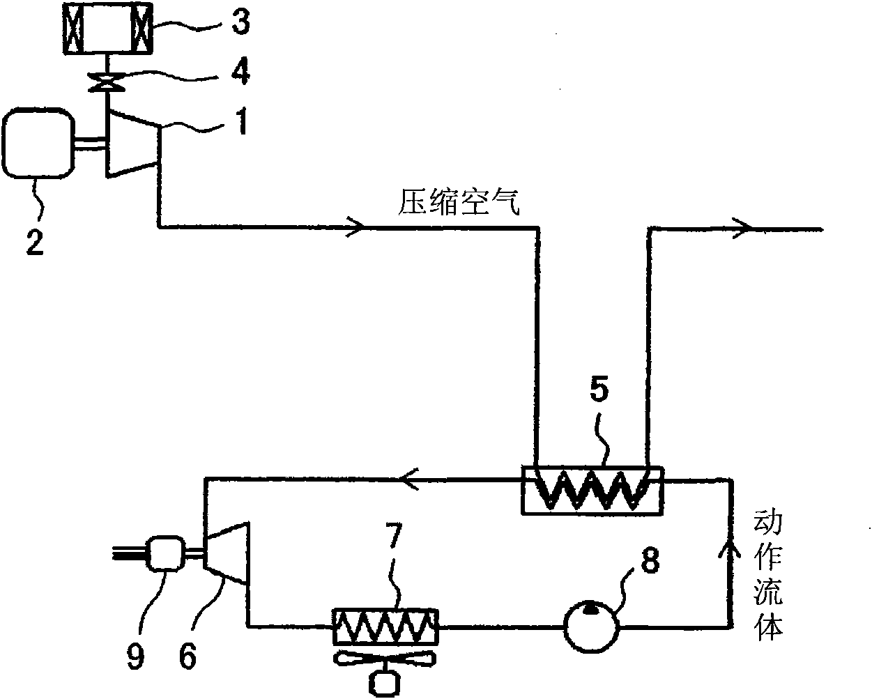
[0051] use figure 1 The first embodiment of the present invention will be described. figure 1 It is a schematic diagram showing the structure of the main part of the compressor of this embodiment.

[0052] At that figure 1 Among them, the non-oil supply and non-water supply type compressor includes a propeller-type compressor main body 1, an electric motor 2 connected to the compressor main body 1 via a transmission device (speed increasing device) not shown, and which drives the compressor main body 1 , And a suction filter 3 and a suction regulating valve 4 provided on the suction side of the compressor body 1. When the compressor body 1 is driven by the electric motor 2, air (atmosphere) is sucked in through the suction filter 3 and the suction regulating valve 4, compressed to a predetermined pressure, and discharged. In addition, the unillustrated control device switches the suction control valve 4 from the open state to the closed state to switch from the load operation to ...


PUM


Abstract

The invention provides a compressor capable of improving exhaust heat recover efficiency. The compressor is provided with a compressor main body (1) for compressing air, and further comprises a heat exchanger (5) for cooling the compressed air exhausted by the compressor main body (1) by performing heat exchange with a working fluid; an expander (6) for expanding the working fluid which is gasified after being heated by the heat exchanger (5) and generating driving force; a condenser (7) for cooling and liquefying the working fluid supplied by the expander (6) and supplying the liquefied working fluid to the condenser (7) of the heat exchanger (5); and a circulating pump (8) for leading the working fluid to circulate among the heat exchanger (5), the expander (6) and the condenser (7). A Rankine cycle is formed by the heat exchanger (5), the expander (6), the condenser (7) and the circulating pump.

Description

technical field [0001] The present invention relates to compressors for compressing gases, and more particularly to compressors for recovering the heat rejected (also called rejected or waste heat). Background technique [0002] A compressor generates a large amount of heat when compressing air, for example, and the compressed air becomes high temperature. Compressed air is sometimes used while maintaining a high temperature, but in general, it is cooled to close to the atmospheric temperature, further dehumidified, and used. Moreover, in a compressor, oil and water are sometimes used for lubrication and cooling, and high-temperature oil and water are cooled. In this way, the heat generated in the compressor is discharged through compressed air, oil, water, etc. However, as a device for recovering the waste heat, a structure in which a thermoelectric conversion element is installed on the main body of the compressor and the discharge piping (for example, refer to Patent Do...

Claims


Application Information

Patent Timeline
IPC IPC(8): F04C29/04
CPCF04C25/00F04C29/04F04C23/006Y02P80/15F01K13/00F04D29/5833F04D29/584
Inventor 纸屋裕治
Owner HITACHI IND EQUIP SYST CO LTD
Why Eureka
Try Eureka