
Two-phase shock wave swing link movable-teeth compound transmission speed reducer

A movable tooth compound, shock wave technology, applied in the direction of gear transmission, transmission, belt/chain/gear, etc., can solve the problem of easy gluing failure of movable tooth transmission, reduced heat generation of movable tooth transmission, and increased transmission ratio of reducer. Large and other problems, to achieve the effect of compact structure, reduce heat generation and temperature rise, reduce input speed

Inactive Publication Date: 2011-01-12
SICHUAN UNIV
View PDF6 Cites 12 Cited by
  • Summary
  • Abstract
  • Description
  • Claims
  • Application Information

AI Technical Summary

Problems solved by technology

The use of a two-phase shock wave solves the vibration and noise caused by the mass eccentricity of the single-phase shock wave in the movable tooth transmission. The shock wave is embedded with a pre-reduction device, which not only increases the transmission ratio of the reducer, but also enables Due to the reduction of speed, the calorific value and temperature rise of the transmission are reduced, thus solving the bottleneck problem that the movable tooth transmission cannot be popularized and applied due to serious high-speed heat generation and easy gluing failure.

Method used


Image

  • Two-phase shock wave swing link movable-teeth compound transmission speed reducer
  • Two-phase shock wave swing link movable-teeth compound transmission speed reducer
  • Two-phase shock wave swing link movable-teeth compound transmission speed reducer

Examples


Embodiment Construction

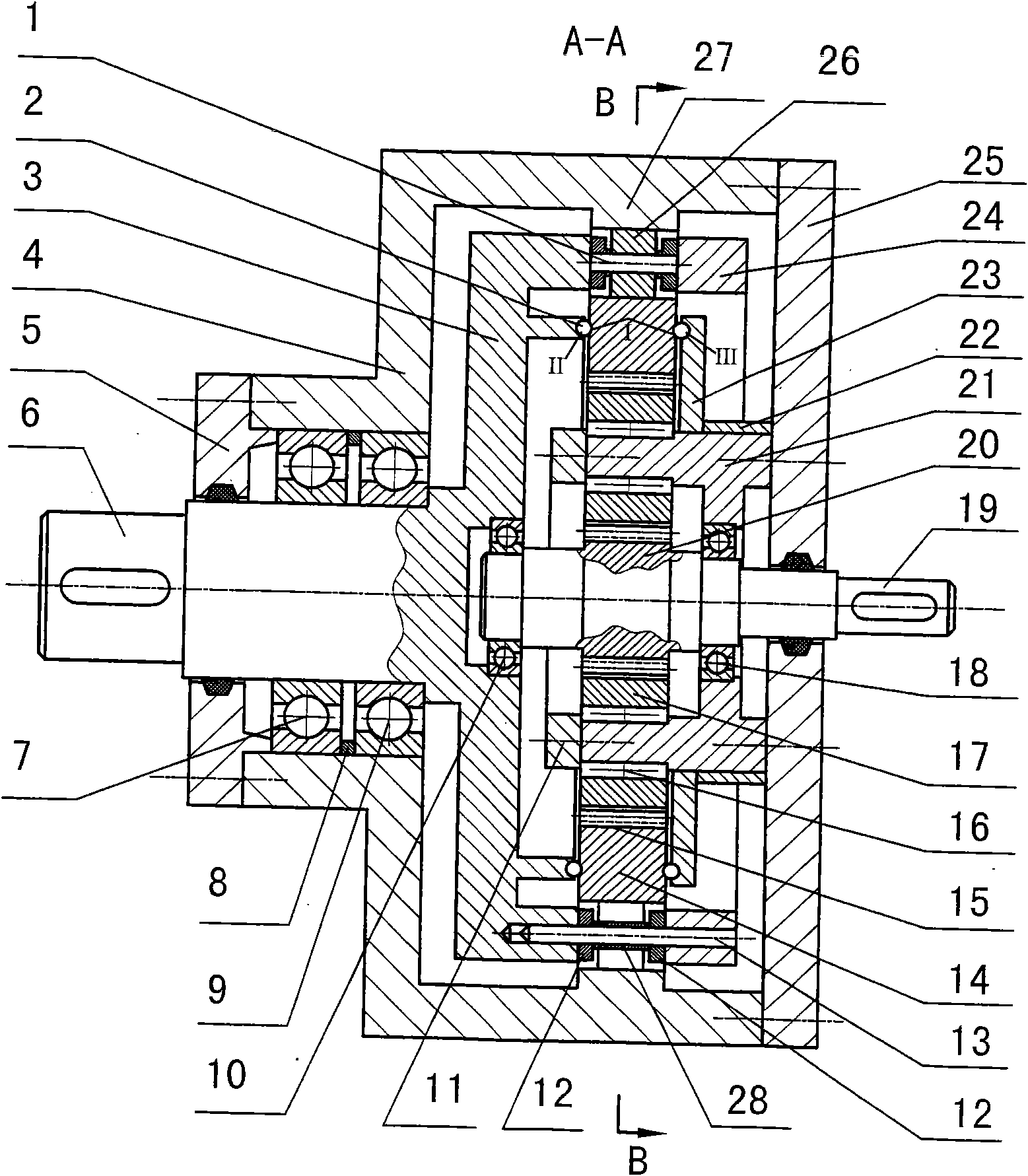
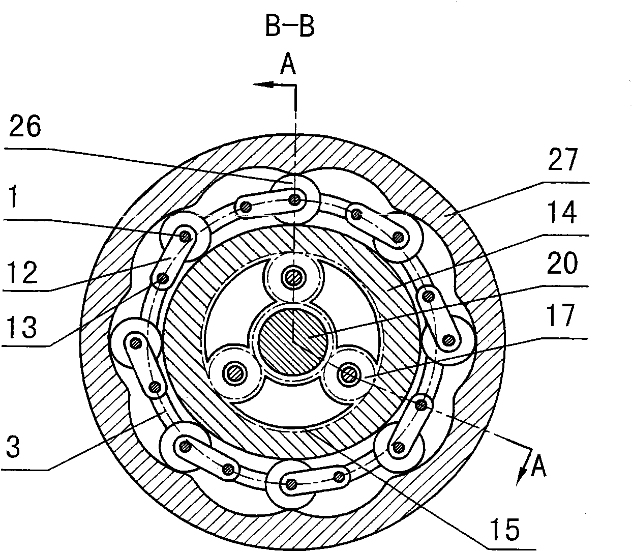
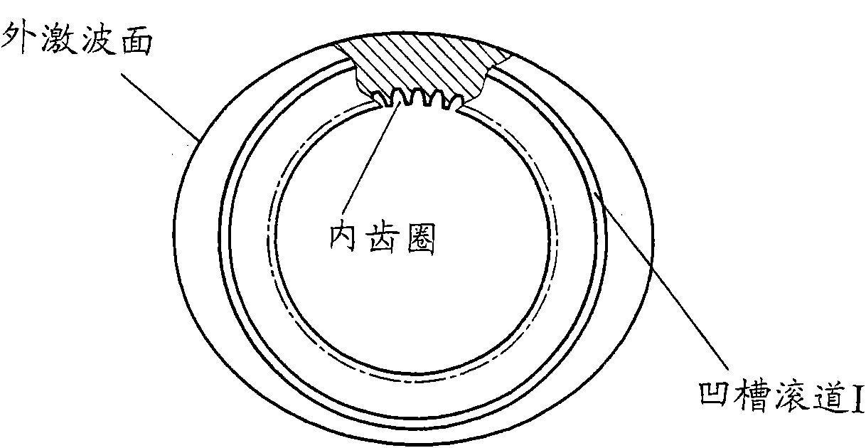
[0040] exist figure 1 and figure 2 Among them, the dual-phase shock wave swing rod movable tooth compound transmission reducer consists of movable tooth pin shaft (1), thrust ball bearing (2) (axial positioning device for dual-phase shock wave device), movable gear rack (3), box body (4), bearing end cover (5), output shaft (6), rolling bearing (7), gasket (8), rolling bearing (9), (10), needle roller limit plate (11), swing rod (12 ), pendulum pin (13), duplex shock (14), ring gear (15), needle bearing (16), pinion (17), rolling bearing (18), input shaft (19), Input gear (20), pinion bracket (21), sleeve (22), thrust plate (23), floating plate (24), case cover (25), movable tooth (26), center wheel (27) and pendulum Rod pin shaft sleeve (28) etc. are formed. Several swing rod pins (13) (the number of swing rod pins are equal to the number of movable teeth) are evenly distributed in the circumferential direction, one end is fixed in the movable gear frame (3), and the othe...


PUM


Abstract

The invention discloses a two-phase shock wave swing link movable-teeth compound transmission speed reducer and relates to the technical field of mechanical transmission. The compound transmission speed reducer mainly comprises a two-phase shock wave device, movable teeth, a swing link, a pin shaft, a movable-teeth frame, a central wheel and a fixed axis gear train which is embedded into the shock wave device. The exterior of the shock wave device has a cam profile and the interior of the shock wave device has an inner gear ring profile; an input gear is engaged with a pinion and the pinion is engaged with the inner gear ring so as to form the fixed axis gear train; the input gear and an input shaft are integrated; the rotation of the input gear is decelerated through the fixed axis gear train and drives the shock wave device to rotate; the shock wave device and the movable teeth are in rolling contact engagement, so that the movable teeth swing along with the swing link and moves along the tooth profile of the central wheel simultaneously; and the shock wave device and the central wheel coact to make the movable teeth drive the movable-teeth frame to rotate and output power through the swing link. By setting pre-deceleration in swing link movable-teeth transmission, the transmission ratio is increased, and the problem of over-high temperature rise of movable-teeth transmission is also solved; and the speed reducer has the advantages of novel and compact structure, high bearing capacity, self-balancing stress and the like, and is suitable for decelerating transmission between two coaxial shafts.

Description

technical field [0001] The invention relates to a two-phase shock swing rod movable tooth compound transmission reducer, which is used to realize the fixed-ratio transmission between two coaxial shafts, and belongs to the technical field of mechanical transmission. Background technique [0002] The pendulum movable tooth drive recently proposed by Chinese scholars is a one-tooth difference swing rod movable tooth transmission. This new type of transmission, like other movable tooth transmissions, has the advantages of compact structure, strong bearing capacity, and high transmission efficiency, but it also has other movable tooth transmissions. There are common problems in the transmission. These problems are limited by the mechanism. The transmission ratio of the single-stage transmission is low, the heat is serious at high speed, and it is easy to cause gluing, so its superiority cannot be exerted. One-tooth-difference pendulum-rod movable-tooth transmission is also becaus...

Claims


Application Information

Patent Timeline
IPC IPC(8): F16H1/28
Inventor 梁尚明黄博
Owner SICHUAN UNIV
Learn More