LED lamp for eliminating glare

A technology of LED light tubes and LED modules, applied in the field of LED light tubes, can solve problems such as waste, increased light loss, and difficulty in eliminating glare, and achieve the effects of soft light, low light loss, and increased light extraction rate

Inactive Publication Date: 2011-01-12
FUJIAN WANBAN OPTOELECTRONICS TECH
View PDF0 Cites 10 Cited by
  • Summary
  • Abstract
  • Description
  • Claims
  • Application Information

AI Technical Summary

Problems solved by technology

Although the height of the LED light tube is high, it has strong glare, which is rather dazzling. The light glare emitted by the LED components of the LED light tube is strong. The most fundamental reason is that the light emitted by the LED chip is mainly concentrated on the upper surface of the LED chip, about It accounts for about 60%. From the perspective of the LED lens, this part of the light emitted is more concentrated, so it looks very dazzling, which affects the promotion of LED light tubes to a certain extent, but eliminating glare is another problem in the industry. Some manufacturers use a lampshade package with frosted gauze. Although this package method achieves the purpose of eliminating glare to a certain extent, this package will lead to increased light loss, which is generally about 50%, resulting in great waste

Method used


Image

  • LED lamp for eliminating glare
  • LED lamp for eliminating glare
  • LED lamp for eliminating glare

Examples


Embodiment 1

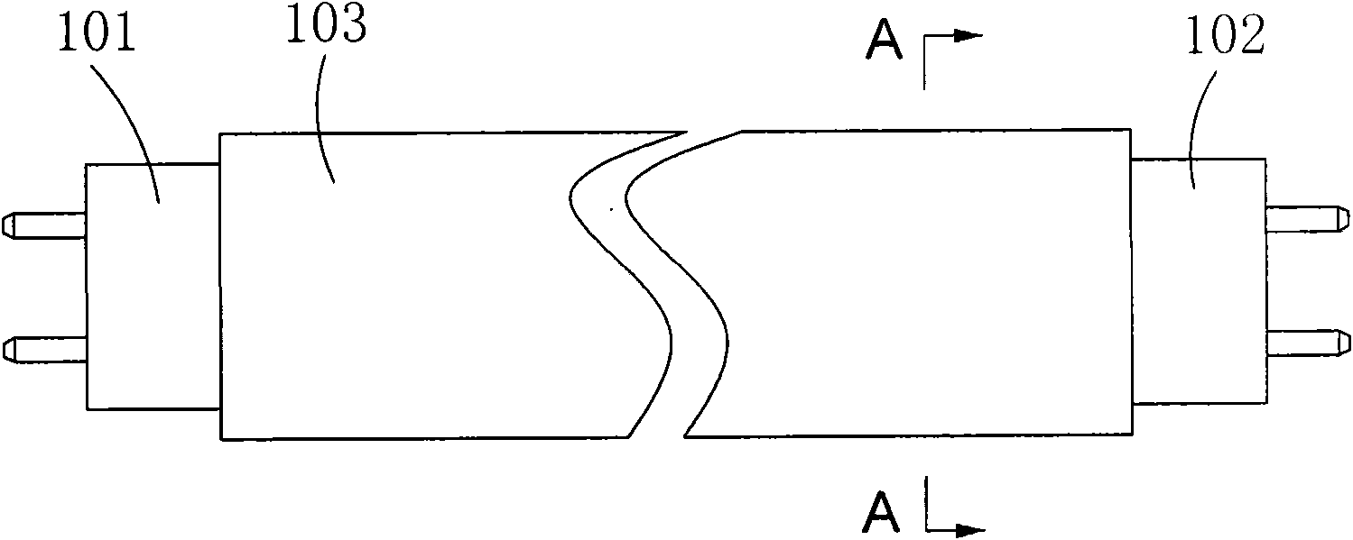
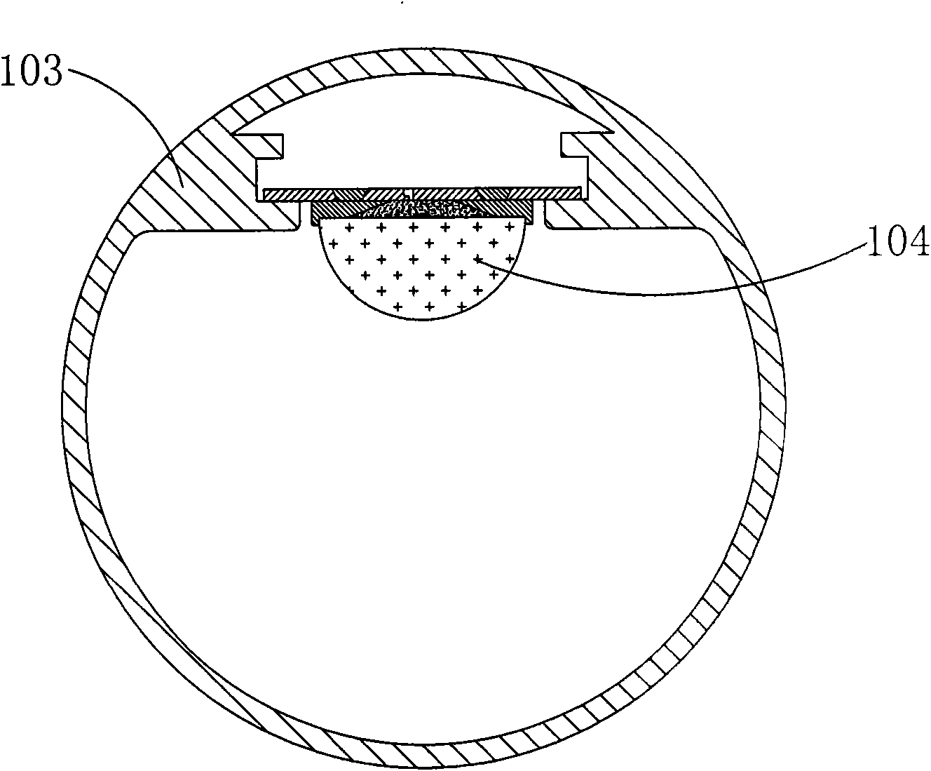
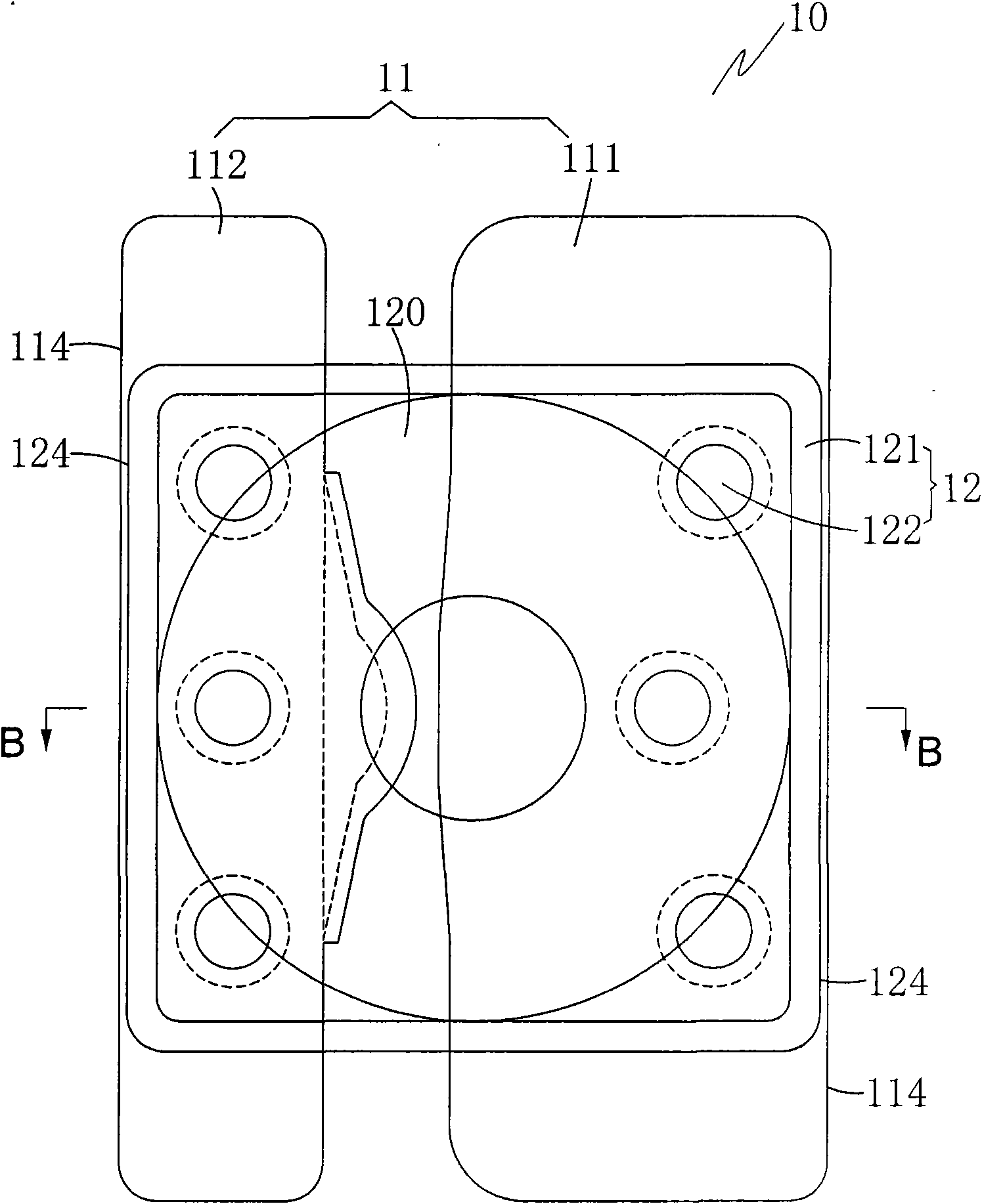
[0027] to combine Figure 1 to Figure 3 As shown, this figure provides a series-connected module 104 structure of the lamp tube 100, the positive plate 111 of the aluminum substrate 11 of any one of the base unit 10 in the base 1 of the lamp tube 100 in this embodiment The negative electrode plate 112 of the aluminum substrate 11 of the adjacent base unit 10 is pressed side by side to form a series connection.

Embodiment 2

[0029] to combine figure 1 , figure 2 and Figure 4 as shown, Figure 4 A series module 104 structure of the lamp tube 100 is also provided, which is an improved structure of the base 1 of the module 104 in the first embodiment, and the positive plate 111 of the aluminum substrate 11 of any one of the base units 10 A series plate 113 is integrally formed with the negative plate 112 which is closely connected side by side with the positive plate 111 , and this series connection is more stable.

Embodiment 3

[0031] to combine figure 1 , figure 2 and Figure 4 as shown, Figure 5 The lamp tube 100 is provided with a parallel module 104 structure, the positive plate 111 of the aluminum substrate 11 of any one of the base monomers 10 in the base 1 of the lamp tube 100 in this embodiment is connected to the adjacent base monomer 1 The positive plates 111 of the aluminum base plate 11 are closely connected side by side. In addition, the negative plate 112 of the aluminum base plate 11 of any base unit 10 is connected side by side with the negative plate 112 of the aluminum base plate 11 of the adjacent base unit 10 to form a parallel connection.


PUM


Abstract

The invention relates to a LED lamp for eliminating glare, which comprises a base, wherein a plurality of light reflecting cups are arranged on the base; a LED chip is arranged at the bottom of each light reflecting cup, and a fluorescent powder layer is coated above each LED chip; a light reflecting sheet is arranged on the surface of each fluorescent powder layer; and the surface of either light reflecting sheets is parallel and level with that of the corresponding fluorescent powder layer. In the LED lamp, a reversal light reflecting layer is formed on the upper part of the fluorescent powder layer additionally through a plurality of light reflecting sheets, so that a high light-emitting part of each LED chip can diffuse well towards periphery and is reflected finally, light rays are soft and are not dazzling, and the loss of light can be ensured to be minimum.

Description

【Technical field】 [0001] The invention relates to a lighting device, in particular to an LED lamp tube for eliminating glare. 【Background technique】 [0002] LED lamps have the characteristics of high brightness, low power consumption, and long life, and their performance in all aspects far exceeds that of ordinary fluorescent lamps, so they have been widely used. Although the height of the LED light tube is high, it has strong glare, which is rather dazzling. The light glare emitted by the LED components of the LED light tube is relatively strong. The most fundamental reason is that the light emitted by the LED chip is mainly concentrated on the upper surface of the LED chip. It accounts for about 60%. From the perspective of the LED lens, this part of the light emitted is more concentrated, so it looks very dazzling, which affects the promotion of LED light tubes to a certain extent, but eliminating glare is another problem in the industry. Some manufacturers use a lampsh...

Claims


Application Information

Patent Timeline
Patent Type & Authority Applications(China)
IPC IPC(8): F21S2/00F21V9/10F21V7/00F21V5/04F21V19/00F21Y101/02F21V9/40
Inventor 何文铭
Owner FUJIAN WANBAN OPTOELECTRONICS TECH
Why Eureka
Try Eureka