Control circuit of quick ignition device of gas cooker

A rapid ignition and control circuit technology, applied to heating fuel, household stove/stove, gaseous heating fuel, etc., can solve problems such as safety hazards, gas leakage, and reducing the safety of gas cookers, so as to prevent gas leakage and ensure The effect of gas safety, improving the safety and reliability of use

Active Publication Date: 2012-05-30
NINGBO FOTILE KITCHEN WARE CO LTD
View PDF0 Cites 0 Cited by
  • Summary
  • Abstract
  • Description
  • Claims
  • Application Information

AI Technical Summary

Problems solved by technology

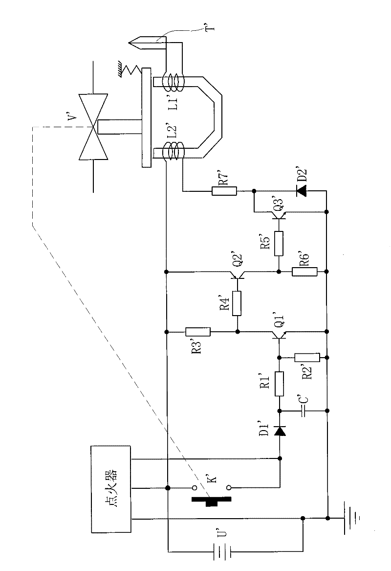
However, there are certain potential safety hazards in the above-mentioned circuit in actual use. Since the conduction of the triode Q1', the triode Q2' and the triode Q3' are interlocking, that is, when the triode Q1' is turned on, the triode Q2' and the Transistor Q3' is turned on immediately, once an accidental short circuit occurs between the collector c and emitter e of triode Q1' due to component failure, then triode Q2' and triode Q3' will remain on, at this time, coil L2' In this case, the solenoid valve V' keeps on until the power supply of the igniter is not enough to maintain the circuit.
Therefore, once any one of the triode Q1', triode Q2' and triode Q3' fails and short-circuits, the gas valve will be permanently closed, and there is a serious risk of gas leakage, which greatly reduces the safety of the gas cooker.

Method used


Image

  • Control circuit of quick ignition device of gas cooker
  • Control circuit of quick ignition device of gas cooker
  • Control circuit of quick ignition device of gas cooker

Examples


Embodiment Construction

[0024] The present invention will be further described in detail below in conjunction with the accompanying drawings and embodiments.

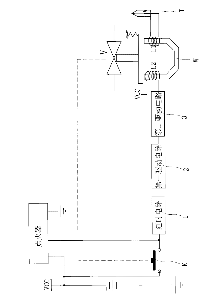
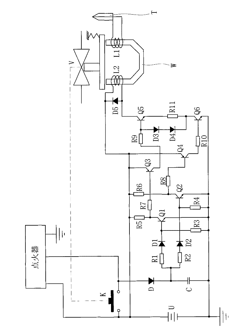
[0025] Such as figure 1Shown is the schematic circuit diagram of the embodiment of the present invention. The ignition device of the gas stove in this embodiment is provided with a delay circuit and a thermocouple, which not only has the function of rapid ignition, but also can effectively prevent accidental flameout after the ignition switch is turned off. Among them, the control circuit of the ignition device includes

[0026] The power supply U of the igniter is taken from the battery on the gas cooker, and the ignition switch K is connected in series to the power circuit of the igniter. After the ignition switch K is closed, the igniter will generate a high-voltage pulse signal to the ignition needle (in the figure not shown);

[0027] Solenoid valve V, which includes a U-shaped electromagnetic core W and a first coil L1 and a second co...


PUM


Abstract

The invention discloses a control circuit of a quick ignition device of a gas cooker. The control circuit comprises an ignitor, an electromagnetic valve, a time delay circuit and a first drive circuit, wherein the electromagnetic valve is coupled with a first coil and a second coil; an input end of the first drive circuit is connected with an output end of the time delay circuit; the control circuit is characterized by also comprising a second drive circuit, wherein the input end of the second drive circuit is connected with the first drive circuit; and the output end of the second drive circuit is in series connection with the second coil. Compared with the prior art, the control circuit has the advantages that: one path of originally independent drive circuit is designed into the first drive circuit and the second drive circuit which are independent of each other and are connected in series; when the ignition circuit works, the electromagnetic valve can only be attracted when the first drive circuit and the second drive circuit are simultaneously switched on; and if a switching element of the first drive circuit is short-circuited, the first drive circuit is failed, because the second drive circuit can still work normally, normal power-down of the second coil of the electromagnetic valve can also be ensured after the ignition switch is disconnected; and thus the electromagnetic valve can be ensured to be under control.

Description

technical field [0001] The invention relates to an ignition circuit of a gas cooker, in particular to a control circuit of a quick ignition device for a gas cooker with accidental flameout protection. Background technique [0002] After more than ten years of development in the gas cooker industry, from the initial ceramic igniter to the later electronic igniter, and then to the latest ion induction needle igniter and thermocouple igniter, as people's awareness of the safety of cooker use continues to increase, The design safety performance of the ignition device for burning appliances has also been greatly improved. [0003] There are two main types of gas stoves currently on the market: one is the more traditional thermocouple type, which has a safe and reliable structure, but the thermocouple itself has a large heat capacity and is inert to temperature changes. Be sure to press the knob and wait for a few seconds until the temperature of the thermocouple rises enough to ...

Claims


Application Information

Patent Timeline
Patent Type & Authority Patents(China)
IPC IPC(8): F24C3/12
Inventor 方献良罗应齐王式兴茅忠群诸永定
Owner NINGBO FOTILE KITCHEN WARE CO LTD
Why Eureka
Try Eureka