Relay device, communication system, and communication method

A relay device, a technology for transmitting signals, applied in communication systems and communication fields, can solve the problems of high carrier frequency, radio waves cannot reach the base station from the terminal, etc., and achieve the effect of good transmission characteristics

Inactive Publication Date: 2011-01-12
SHARP KK
View PDF5 Cites 5 Cited by
  • Summary
  • Abstract
  • Description
  • Claims
  • Application Information

AI Technical Summary

Problems solved by technology

[0004] The next generation of mobile communication is likely to have a higher carrier frequency, which makes it impossible for radio waves to reach the base station from the terminal (or from the base station to the terminal)

Method used


Image

  • Relay device, communication system, and communication method
  • Relay device, communication system, and communication method
  • Relay device, communication system, and communication method

Examples


no. 1 example

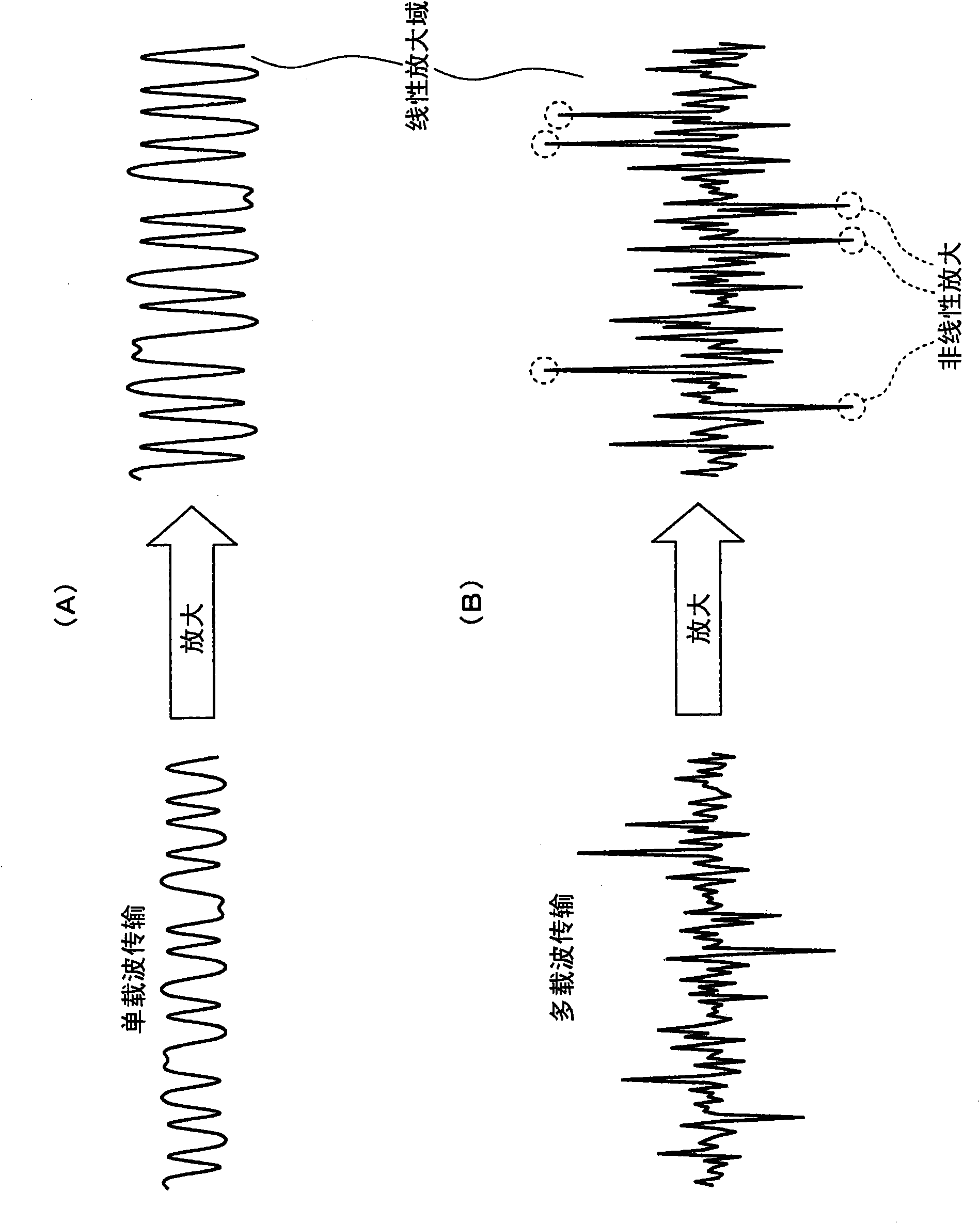
[0056] figure 1 is a graphical representation of a single-carrier signal waveform compared to a multi-carrier signal waveform. figure 1 (A) is a waveform diagram of a single carrier signal, figure 1 (B) is a waveform diagram of a multi-carrier signal.

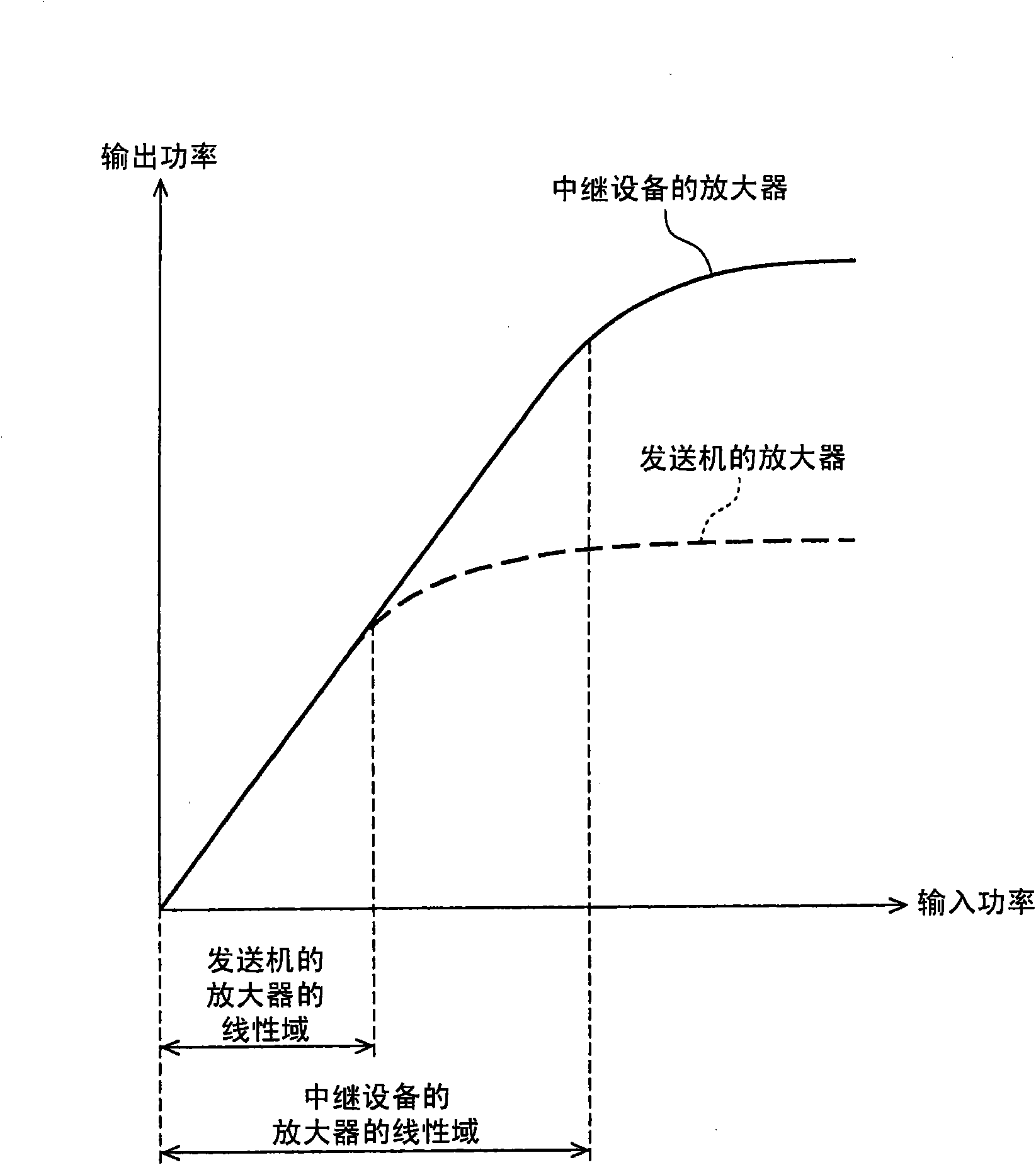
[0057] In multicarrier transmissions such as OFDM and MC-CDMA, independently modulated carriers are superimposed such that the PAPR increases with the number of subcarriers. Therefore, in the case of using an amplifier with a narrow linear amplification range, such as figure 1 As shown in (A), a single-carrier signal can be amplified without any distortion, while as figure 1 As shown by the dashed line in (B), multi-carrier signals are distorted because signals outside the linearly amplifiable region cannot be linearly amplified.

[0058] Transmission of a signal distorted by an amplifier results in deterioration of transmission characteristics. Using an amplifier with a wider linear domain increases the size and cost...

no. 2 example

[0077] Although the above description about the first embodiment is for the case where the relay station 1 does not perform bit demodulation, a configuration in which the relay station performs symbol-to-bit demodulation may also be adopted. In this embodiment, a configuration example in which a communication system performs symbol-to-bit demodulation and generates and transmits symbol replicas will be described.

[0078] Figure 10 is a block diagram of a configuration example of the relay station 1 according to the second embodiment of the present invention. In the figure, a relay station 1 includes antennas 11 and 15 , a single-carrier signal receiving section 12 , a converting section 16 and a multi-carrier signal transmitting section 14 . The single carrier signal receiving section 12 includes a radio receiving section 121 , a GI removing section 122 , a DFT section 123 , a pilot signal extracting section 124 , an equalizing section 125 , a weight calculating section 126...

no. 3 example

[0089] In a case where the channel environment between the relay station and the base station is bad, a configuration in which the relay station performs error correction decoding processing may be employed. The present embodiment will be described for a configuration example of a communication system in which a relay station performs error correction decoding.

[0090] Figure 14is a block diagram of a configuration example of a relay station according to the third embodiment of the present invention. In this figure, a relay station 1 includes antennas 11 and 15 , a single-carrier signal receiving section 12 , a converting section 17 and a multi-carrier signal transmitting section 14 . The single carrier signal receiving section 12 includes a radio receiving section 121 , a GI removing section 122 , a DFT section 123 , a pilot signal extracting section 124 , an equalizing section 125 , a weight calculating section 126 and an IDFT section 127 . The multicarrier signal transm...


PUM


Abstract

Even when an amplifier has a comparatively narrow linear region in a terminal, it is possible to suppress degradation of the transmission characteristic by using single-carrier transmission between the terminal and a relay device while using multi-carrier transmission between the relay device and a base station in an uplink of a communication system. The relay station (1) includes: a single-carrier signal reception unit (12) which receives a single-carrier signal from the terminal and performs signal processing; a conversion unit (13) which converts a time region symbol outputted from the single-carrier signal reception unit (12) into a frequency region symbol; and a multi-carrier signal transmission unit (14) which makes the symbol converted by the conversion unit (13) to be a multi-carrier signal and transmits the multi-carrier signal to the base station.

Description

technical field [0001] The present invention relates to a relay device, a communication system, and a communication method, as well as a relay device for converting a single-carrier signal from a terminal into a multi-carrier signal for output, a communication system having the relay device, and a a method of communication. Background technique [0002] In recent years, technologies such as OFDM (Orthogonal Frequency Division Multiplexing) or MC-CDMA (Multi-Carrier Code Division Multiple Access) have been able to ensure good Multi-carrier transmission of transmission characteristics has attracted attention in the field of radio communication. [0003] However, the PAPR (Peak-to-Average Power Ratio) of a multi-carrier signal is high, so the nonlinearity of the amplifier becomes a problem. On the other hand, single-carrier transmission is becoming an uplink (transmission from terminal to base station) transmission technology of interest due to its low PAPR. [0004] The nex...

Claims


Application Information

Patent Timeline
Patent Type & Authority Applications(China)
IPC IPC(8): H04J11/00H04B7/208
CPCH04L5/0007H04L25/20H04L27/36H04L25/03159H04B7/15542H04L27/2614H04B7/2606H04L5/0028H04L25/0228H04L2025/03414H04L25/067
Inventor 中村理野上智造山田良太
Owner SHARP KK
Why Eureka
Try Eureka