Gradual die-less forming method

A dieless forming and progressive technology, which is applied in the field of dieless progressive extrusion, can solve the problems of inconvenient control, complex structure of forming mechanism, and low precision of the workpiece, and achieve the advantages of easy control, improved scope of application, and improved precision. Effect

Inactive Publication Date: 2011-01-19
ZHEJIANG UNIV OF TECH
View PDF7 Cites 21 Cited by
  • Summary
  • Abstract
  • Description
  • Claims
  • Application Information

AI Technical Summary

Problems solved by technology

[0009] The purpose of the present invention is to overcome the defects of complex structure of the forming mechanism, inconvenient control and low precision of the formed workpiece existing in the e

Method used


Image

  • Gradual die-less forming method
  • Gradual die-less forming method
  • Gradual die-less forming method

Examples


Embodiment 1

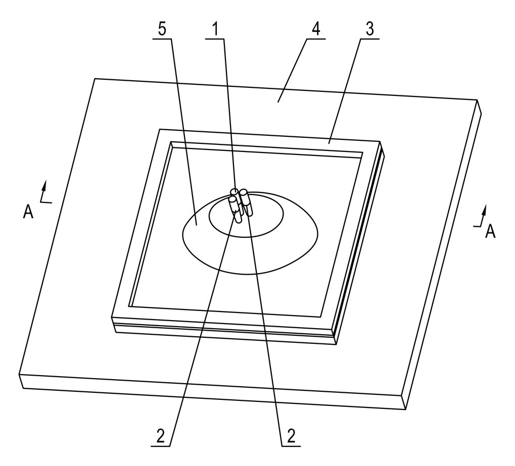
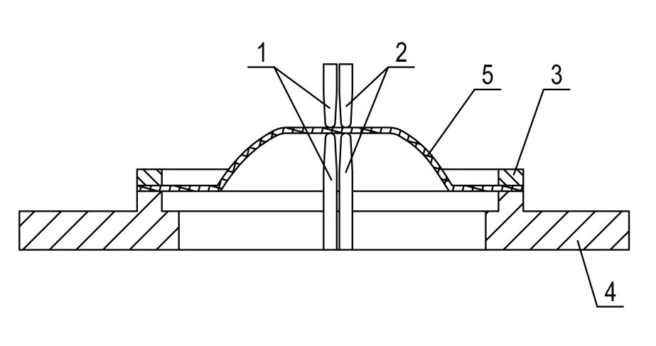
[0030] Example 1: In such as figure 1 , figure 2 In the shown embodiment, a progressive dieless forming method of the present invention adopts a two-way three-point progressive dieless forming method, and three pairs of extrusion forming heads are used to progressively extrude the plate according to a certain trajectory Stretch forming processing, three pairs of extrusion forming heads include the main forming head 1 for forming, and two pairs of auxiliary forming heads 2 located on the right and rear sides of the main forming head. The connecting lines between the axes of the main forming heads are perpendicular to each other, forming a image 3 As shown in the right-angle arrangement, all extrusion forming heads are formed by butting the upper forming head and the lower forming head up and down, and the upper and lower forming heads are respectively arranged on the upper working head above the plate 5 (not shown in the figure). ) and the lower working head (not shown in t...

Embodiment 2

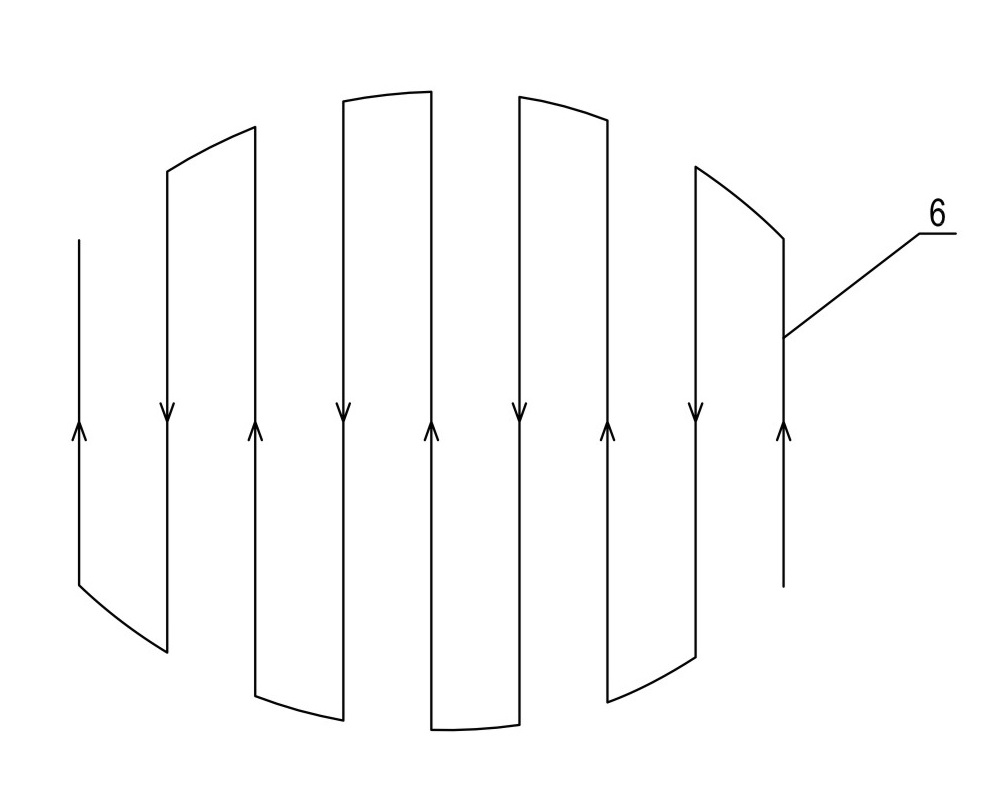
[0032] Embodiment 2: In this embodiment, the arrangement of the extrusion molding head and the heating device is the same as that of Embodiment 1. In order to simplify the motion trajectory and facilitate the control of the extrusion molding head and the workbench, the motion trajectory 6 of this embodiment can be obtained in the following manner: start from one side of the three-dimensional contour with a vertical plane perpendicular to the horizontal X-axis The lower surface is sectioned and moved to the other side of the three-dimensional contour at a fixed interval T, thereby forming multiple contour lines, and the same contour line has the same X coordinate, and the projection of the contour line on the horizontal plane is parallel to Y The longitudinal straight line of the axis, and become the movement trajectory during sheet metal processing, the arrangement of the movement trajectory is as follows Figure 5 As shown, in addition, the height coordinates for controlling ...


PUM


Abstract

The invention discloses a gradual die-less forming method suitable for small-batch single plate forming processing. The method adopts the following technical scheme: the plate needing to be processed, under the control of a numerical control system, moves in the plane according to the set processing path; to match with the horizontal movement of the plate; three couples of extrusion forming heads, under the control of the numerical control system, independently move along the vertical direction according to the paths set by self to carry out continuous gradual extrusion drawing forming on theplate; each couple of extrusion forming heads comprises an upper forming head and a lower forming head; the upper forming heads and the lower forming heads, opposite to each other, are respectively arranged on an upper working head above the plate and a lower working head below the plate; and the three couples of extrusion forming heads comprise one couple of main forming heads for forming and two auxiliary forming heads which are near the main forming heads and used for clamping and positioning the plate. The method can carry out two-way drawing forming on the plate and the auxiliary formingheads clamp, position and correct the formed area of the plate, thus improving the formed shape and dimension precision.

Description

[0001] technical field [0002] The invention relates to rapid forming processing of metal plates, in particular to a method for extrusion forming in a dieless progressive manner. [0003] Background technique [0004] In the field of mechanical processing, the stamping process has the advantages of material saving, fast and efficient, which is conducive to reducing manufacturing costs. The existing stamping process mainly includes punching and stretching. Due to the high manufacturing cost and long cycle of the mold, the above-mentioned process method is only suitable for mass production. For single-piece or small-batch processing, the traditional method is that skilled workers use some simple tools to hammer by hand. It is not only low production efficiency, but also difficult to guarantee dimensional accuracy. With the advancement of technology, there have been many CNC punching machines that use CNC methods for stamping processing, mainly through continuous stamping of...

Claims


Application Information

Patent Timeline
IPC IPC(8): B21D25/00
Inventor 彭伟李文姚春燕姜献峰章巧芳王明环
Owner ZHEJIANG UNIV OF TECH
Why Eureka
Try Eureka