
Three-layered secondary air low nitrogen oxide swirl burner

A low nitrogen oxide, swirl burner technology, applied in the direction of burner, gas fuel burner, combustion type, etc., can solve problems such as difficulty in ignition, increased production, variable coal quality in power plants, etc., to achieve enhanced fuel classification technology, reduce NOx formation, and enhance the effect of air classification technology

Inactive Publication Date: 2011-01-19
HUAZHONG UNIV OF SCI & TECH
View PDF8 Cites 26 Cited by
  • Summary
  • Abstract
  • Description
  • Claims
  • Application Information

AI Technical Summary

Problems solved by technology

[0004] At present, there are low NO x Swirl burner can effectively reduce NO in lignite and bituminous coal boilers x However, lean coal, anthracite and other low-volatile coals have the characteristics of difficulty in ignition, poor combustion stability, and difficulty in burning out. The conventional means are to strengthen ignition, intensify combustion, and increase thermal intensity, which is of course beneficial to lean coal and anthracite. combustion, but also leads to NO x increase in production and thus existing low NO x Effect of Swirl Burner on NO of Lean Coal / Anthracite Boiler x Mitigation effect is very poor
However, the proportion of lean coal and anthracite boilers in my country's coal-fired power plants is relatively large, and the quality of coal in power plants is variable and poor. poor low volatile coal
Low volatile coal boiler adopts low NO x Swirl burner achieves stable combustion and low NO at the same time x The problem of emissions has not been well resolved so far, and there are few related researches at home and abroad.

Method used


Image

  • Three-layered secondary air low nitrogen oxide swirl burner
  • Three-layered secondary air low nitrogen oxide swirl burner
  • Three-layered secondary air low nitrogen oxide swirl burner

Examples


Embodiment Construction

[0026] Below in conjunction with accompanying drawing and specific embodiment the present invention will be further described

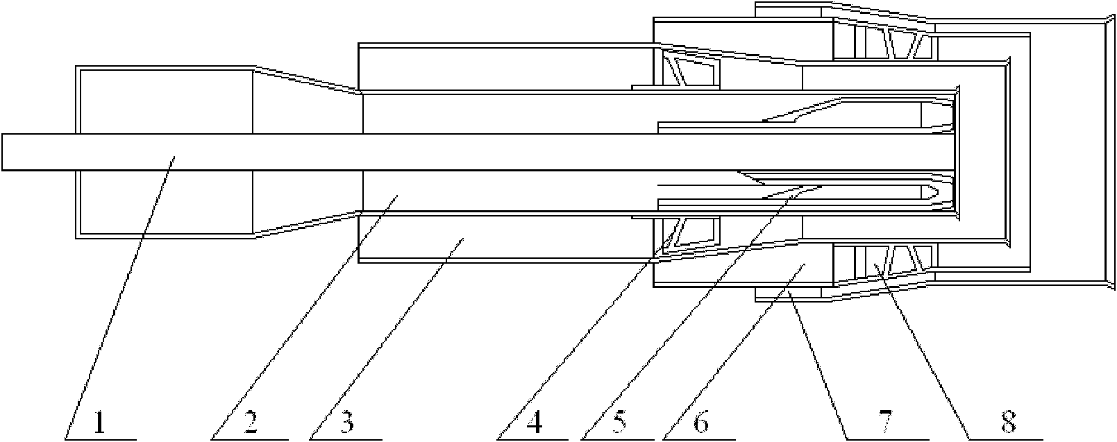
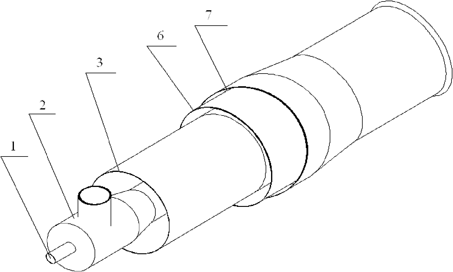
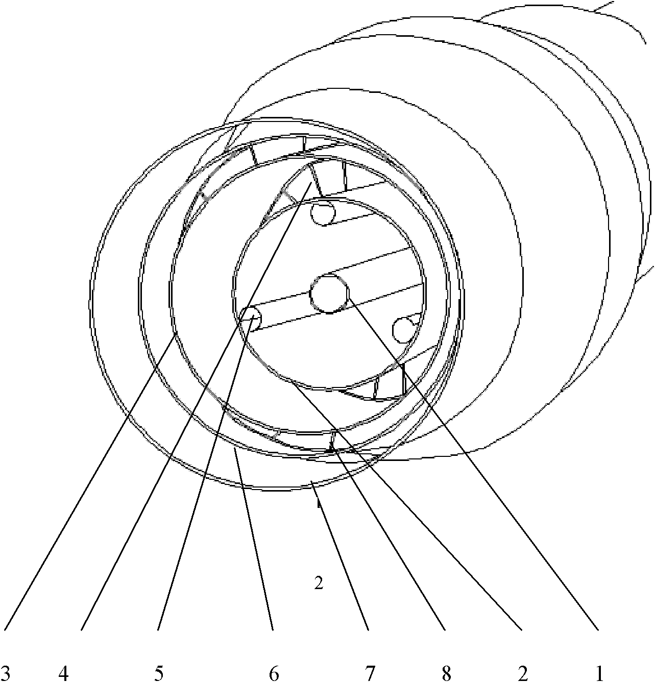
[0027] as attached Figure 1 ~ Figure 3 Shown is a three-layer secondary air low NO x The swirl burner is mainly composed of a central air duct 1, a primary air duct 2, an inner secondary air duct 3, a middle secondary air duct 6 and an outer secondary air duct 7, which are sequentially connected from the inside to the outside. The outlet end of the inner secondary air duct (3) is located downstream of the outlet end of the primary air duct (2), and the outlet end of the secondary air duct (6) is located at the outlet end of the inner secondary air duct (3). Downstream, the outlet of the outer secondary air pipe (7) is located downstream of the outlet of the middle secondary air pipe (6).

[0028] The central air in the central air pipe 1 is direct current, and the central air is not used when the burner is in normal load operation, but is mainly us...


PUM


Abstract

The invention provides a three-layered secondary air low nitrogen oxide (NOx) swirl burner, which consists mainly of: a first-layer center air pipe, a first-layer primary air pipe, an internal secondary air pipe, a middle secondary air pipe, an external secondary air pipe and a third-layer secondary air pipe in a sequentially sleeved manner from inside to outside, wherein the primary air pipe adopts the tangential air feeding manner, an outlet end of the primary air pipe is equipped with a coal dust collector; the internal secondary air pipe and the external secondary air pipe are internally equipped with swirl blades; the outlet ends of the secondary air pipes all have certain angles expanding outwards. With the above structure, the low NOx swirl burner according to the invention can reinforce the local fractional burning effect thereof and increase the quantity of flux of high temperature smoke, thereby ultimately reaching the purpose of stable burning and reduction of NOx generated by burning. The swirl burner according to the invention has strong industrial applicability and wide applicable types of coal, and is particularly suitable for coal used for power in power system in China.

Description

technical field [0001] The present invention relates to nitrogen oxides (NO x ) field of emission control devices, especially relating to a low NO x burner. Background technique [0002] Acidic pollutant gases discharged from coal-fired power plant boilers mainly include SO x , NO x and CO 2 Wait. With the development of my country's economy and technology and the improvement of environmental protection requirements, the NO x Effective control of emissions not only has significant environmental benefits, but also has significant economic and social benefits. It is one of the environmental problems that need to be solved urgently. [0003] From a technical and economic point of view, low NO x Combustion technology has been the most widely used to control coal-fired boiler NO x Emission measures, even in order to meet the emission standards have to use post-combustion flue gas denitrification technology with huge investment and operating costs, still must adopt low NO ...

Claims


Application Information

Patent Timeline
Patent Type & Authority Applications(China)
IPC IPC(8): F23D14/58
Inventor 苏胜向军孙路石胡松
Owner HUAZHONG UNIV OF SCI & TECH
Learn More