Device for preparing multi interbedding rock-soil modeling materials
A model material and rock-soil technology, which is applied in the field of devices for preparing multi-interlayer rock-soil model materials, can solve problems such as the inability to simulate interlayer rock-soil bodies, and achieve the effects of avoiding discreteness, thickness adjustment, and easy thickness
- Summary
- Abstract
- Description
- Claims
- Application Information
AI Technical Summary
Problems solved by technology
Method used
Image

Examples
Embodiment Construction
[0041] The present invention will be described in further detail below in conjunction with the accompanying drawings.
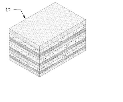
[0042] The basic idea of the present invention is to obtain multi-interlayer model material blocks 17 by uniformly laying a variety of similar materials layer by layer.
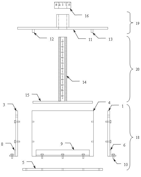
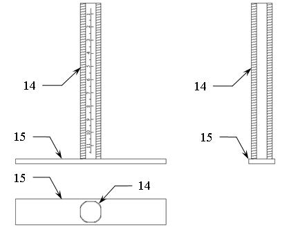
[0043] The main components of the device of the present invention include a material box 18 (connected and combined by the first side plate 1, the second side plate 2, the third side plate 3, the fourth side plate 4, the bottom plate 5 and some fastening bolts 10), Flat push plate 19 (connected and combined by the main frame 11 of the flat push plate and the first strip steel 12 and the second strip steel 13), T-shaped frame 20 (connected and combined by special bolts 14 and the third strip steel 15 ), the adjusting nut 16 is characterized in that: the special bolt 14 of the T-shaped frame 20 passes through the square hole in the middle of the main frame 11 of the flat push plate and then ...
PUM
 Abstract
Description
Claims
Application Information
PatSnap Eureka turns technology decisions into work you can execute. Powered by our Innovation Knowledge Graph, it runs expert workflows across engineering, life sciences, materials and intellectual property. Get your review-ready output in minutes.


