Winding device with plate and winding method

A technology of winding device and strip plate, which is applied in the direction of winding strips, transportation and packaging, coil manufacturing, etc., and can solve problems such as management, clamping rod diameter reduction, plastic deformation, etc.

Inactive Publication Date: 2011-01-19
NITTOKU ENG CO LTD
View PDF5 Cites 5 Cited by
  • Summary
  • Abstract
  • Description
  • Claims
  • Application Information

AI Technical Summary

Problems solved by technology

Therefore, if Figure 9 As shown in (d), when the strip 4 is wound on the winding core 2, the strip 4 is wound linearly at the opening of the locking recess 2a, and the portion straddling the opening is formed as Since it is linear, the inner diameter of the obtained annular core is smaller than the outer diameter of the winding core 2, and it is difficult to control the inner diameter.
In addition, if the magnetic strip 4 is wound several tens of times around the winding core 2, even after the winding core 2 is pulled out, the straight line portion straddling the opening of the locking recess 2a always exists, so

Method used


Image

  • Winding device with plate and winding method
  • Winding device with plate and winding method
  • Winding device with plate and winding method

Examples


Example Embodiment

[0023] Next, the best mode for carrying out the present invention will be described based on the drawings.
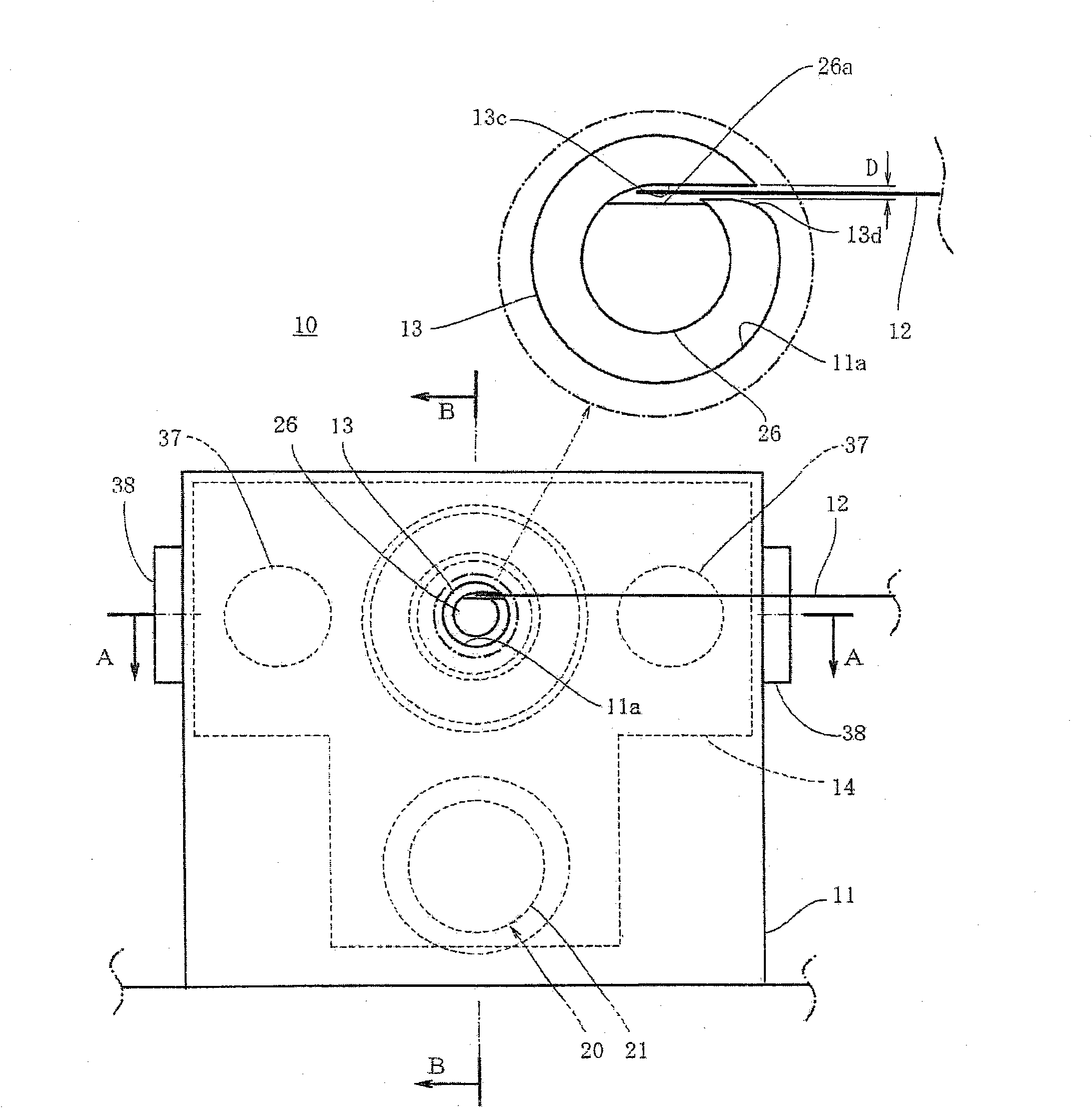
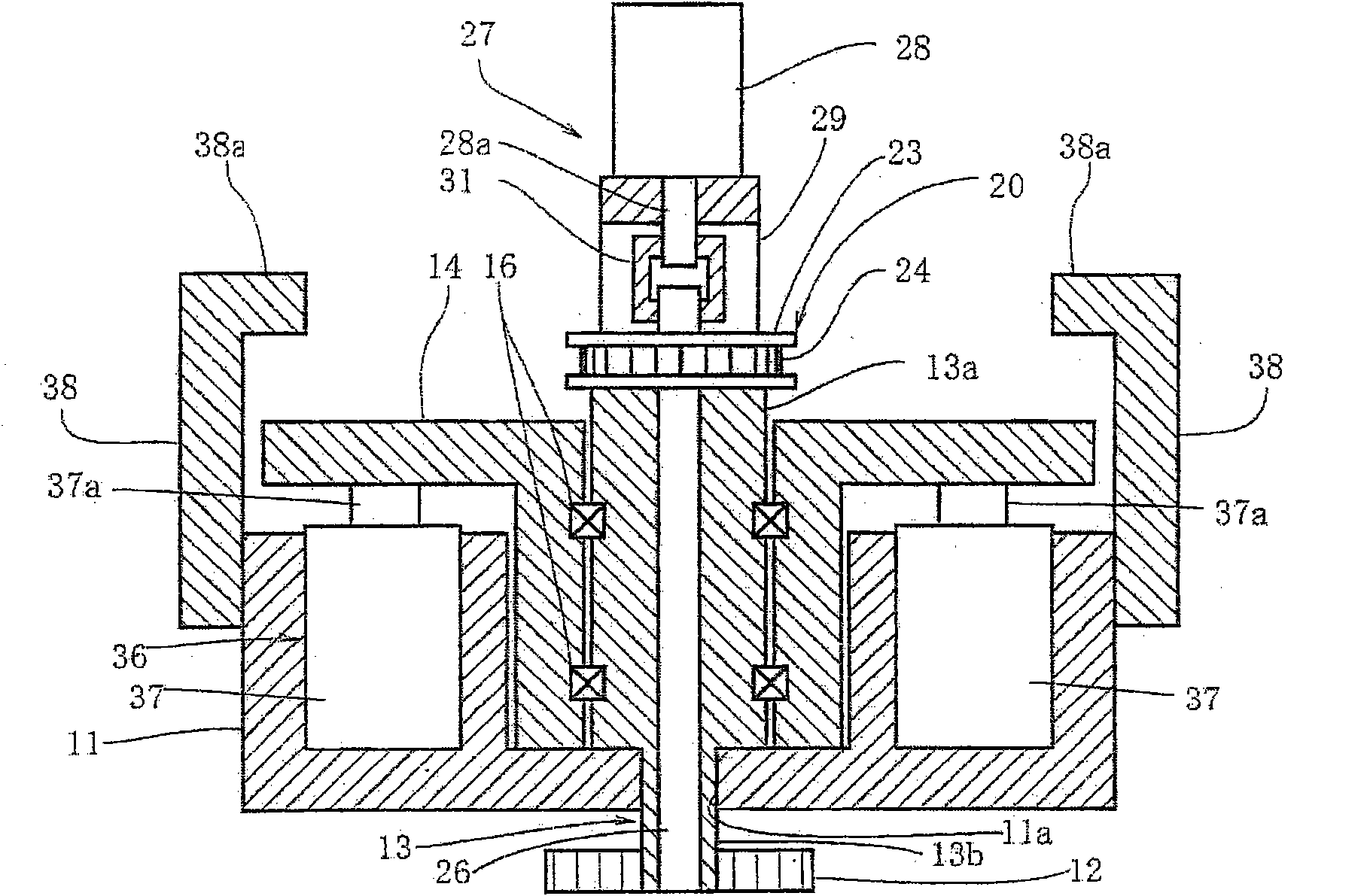
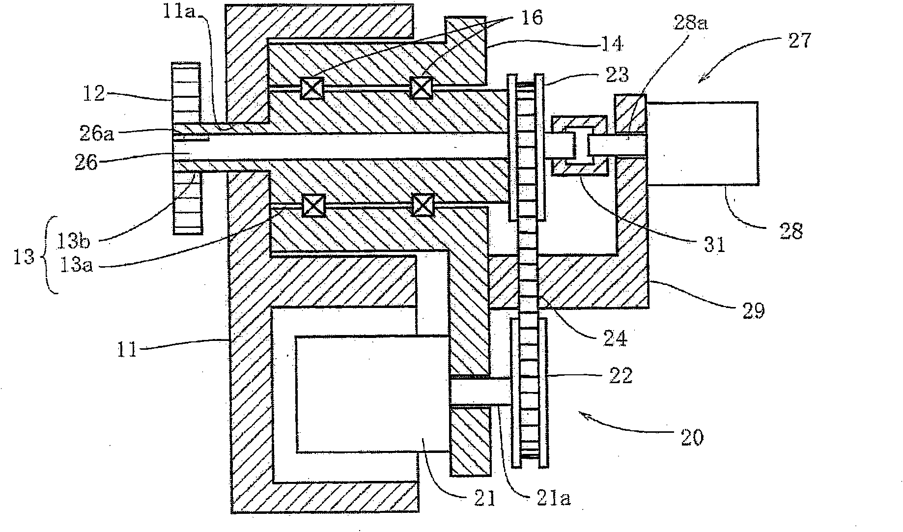
[0024] in Figure 1 ~ Figure 3 The winding device 10 of the present invention is shown in FIG. The strip winding device 10 has a winding core 13 which is provided to be rotatable and whose front end protrudes from the front of a main body 11 made of a rectangular body, and a magnetic strip 12 is wound around the front end. As the magnetic strip plate 12, a strip-shaped thin plate made of amorphous metal or a strip-shaped thin plate made of silicon steel is exemplified. Such as figure 2 and image 3 As shown, a bearing body 14 movable in the axial direction of the winding core 13 is provided on the back side of the main body 11. The winding core 13 has a support cylinder portion 13a and a front end cylinder portion 13b. The support cylinder portion 13a is rotatably supported on the bearing body 14 via a bearing 16, and the front end cylinder portion 13b is continuous wit...


PUM


Abstract

The invention provides a winding device with a plate and winding method to obtain a approximately round iron core whose inner diameter is equal to the outer diameter of a coil core. The winding device with a plate comprises a cylinder-shaped coil core (13), a clamping rod (26) and a clamping rod rotating drive mechanism (27). The coil core is provided with a slit (13c) for a magnetic band plate (12) to insert into from the outer periphery to the inner periphery, and the coil core rotates through a coil core rotating drive mechanism (20) and winds the band plate on the outer periphery. The clamping rod is inserted into the coil core and is provided with a gap (26a) which is communicated to the slit and can be inserted by the front end of the band plate. The clamping rod rotates with respect to the coil core, and the gap moves with respect to the slit and holds the front end of the magnetic plate, and the front end of the magnetic plate is loosened from the gap and from the slit at opposite direction. The winding device with a plate is preferably formed by the tangent of the inner side of the cylinder-type coil of the slit, and a rounding is disposed at the side angle of the obtuse angle between the outer periphery of the coil and the slit.

Description

technical field [0001] The present invention relates to an improvement of a strip winding device and a winding method for winding a strip onto a core. Background technique [0002] For example, a toroidal coil used as an inductor for a power line filter or the like is composed of a toroidal core and a conductive wire wound around the toroidal core via an insulating material. As is well known, conventionally, as an annular core constituting such an annular core, a magnetic strip is wound around a winding core sandwiching the front end of a magnetic strip for several tens of turns, and the winding core is pulled out from the wound magnetic strip. shaped ring core. And, as the coiling method of this strip plate, proposed as Figure 9 The scheme shown (for example, refer to patent document 1). [0003] Specifically, in the winding method of the strip plate, as Figure 9 As shown in (a), the winding core 2 is formed to have a locking recess 2a opened to its outer peripheral sur...

Claims


Application Information

Patent Timeline
IPC IPC(8): H01F41/08B65H18/10B65H75/28
Inventor 谷口智秀
Owner NITTOKU ENG CO LTD
Why Eureka
Try Eureka