Heating cable and extrusion equipment thereof

A technology for heating cables and extrusion equipment, used in insulated cables, bendable cables, cable/conductor manufacturing, etc., and can solve problems such as loose cable cores, reduced tensile strength, and cable shape deformation.

Active Publication Date: 2018-02-16
欧耐特线缆集团有限公司
View PDF10 Cites 4 Cited by
  • Summary
  • Abstract
  • Description
  • Claims
  • Application Information

AI Technical Summary

Problems solved by technology

However, after adding the heat-generating filler material of EPDM rubber with a particle size of 40nm, after using the cable extruder, it is easy to turn over the special-shaped insulating core and cause the twisting of the cable, ...

Method used


Image

  • Heating cable and extrusion equipment thereof
  • Heating cable and extrusion equipment thereof
  • Heating cable and extrusion equipment thereof

Examples


Embodiment 1

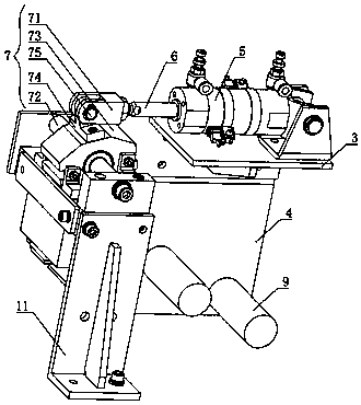
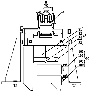
[0031] A heating cable processing and extrusion equipment, comprising an extrusion frame 1, an extrusion mechanism 2 arranged on the extrusion frame 1, the extrusion mechanism 2 includes a first horizontal plate 3, a first vertical plate 4, and an extrusion mechanism The first cylinder 5, the push rod 6, the linkage rod 7, the extrusion head 8 on the horizontal plate 3, the rolling cylinder 9 arranged on the first vertical plate 4, the front end of the first cylinder 5 is connected to the linkage rod 7 through the push rod, The lower end of the linkage rod 7 is connected with the extrusion head 8 .

[0032] The linkage rod 7 includes the first section 71 of the connecting rod, the second section of the connecting rod (not shown in the figure), a bearing rod 72, a hollow fixed bearing 73, a movable bearing 74, and a movable bolt 75, and the bearing rod 72 runs through the fixed bearing 73, The two ends of the bearing rod 72 are respectively connected to the extrusion frame 1, t...

Embodiment 2

[0035] A heating cable processing and extrusion equipment, comprising an extrusion frame 1, an extrusion mechanism 2 arranged on the extrusion frame 1, the extrusion mechanism 2 includes a first horizontal plate 3, a first vertical plate 4, and an extrusion mechanism The first cylinder 5, the push rod 6, the linkage rod 7, the extrusion head 8 on the horizontal plate 3, the rolling cylinder 9 arranged on the first vertical plate 4, the front end of the first cylinder 5 is connected to the linkage rod 7 through the push rod, The lower end of the linkage rod 7 is connected with the extrusion head 8 .

[0036] The linkage rod 7 includes the first section 71 of the connecting rod, the second section of the connecting rod (not shown), a bearing rod 72, a hollow fixed bearing 73, a movable bearing 74, and a movable pin 75. The bearing rod 72 runs through the fixed bearing 73, The two ends of the bearing rod 72 are respectively connected to the extrusion frame 1, the movable bearing ...


PUM

PropertyMeasurementUnit
Particle sizeaaaaaaaaaa

Abstract

The invention discloses a heating cable, and relates to special equipment or methods for manufacturing conductors or cables. The problems of the twisting and the bending of a cable, the non-rounding condition and the instable forming degree of the extruded cable, the loosening of a cable core, the reduced tensile strength and the shape deformation of the cable, due to the turnover of a special-shaped insulating wire core after the adoption of an existing cable extruding machine and the addition of heating and filling materials containing EPDM rubber 40 nm in grain diameter, can be solved. Theheating cable comprises an outer protective layer, an armor layer, an inner protective layer, an insulating layer and a conductor layer, wherein the above layers are sequentially wrapped from outsideto inside. Four to six anti-shielding layers are distributed on the outer ring of the conductor layer. The anti-shielding layers are located between the conductor layer and the insulating layer. Heating and filing materials are filled between the conductor layer and the insulating layer. According to the technical scheme of the invention, the twisting and the bending of the cable, caused by the turnover of the special-shaped insulating wire core, can be avoided. The invention further discloses equipment for machining and extruding the heating cable.

Description

technical field [0001] The invention relates to special equipment or methods for manufacturing conductors or cables, in particular, a heating cable and its extrusion equipment. Background technique [0002] The main production process of power cables (power cord series) has the following steps: [0003] Commonly used copper and aluminum rods for wire and cable, at room temperature, use a wire drawing machine to pass through one or several die holes of the drawing die to reduce the cross section, increase the length and improve the strength. Wire drawing is the first process of each wire and cable company, and the main process parameter of wire drawing is mold matching technology. [0004] When the copper and aluminum monofilaments are heated to a certain temperature, the toughness of the monofilaments is improved and the strength of the monofilaments is reduced by means of recrystallization, so as to meet the requirements of electric wires and cables for conductive cores. ...

Claims


Application Information

Patent Timeline
IPC IPC(8): H01B7/04H01B7/17H01B7/18H01B7/28H01B13/24
CPCY02A30/14H01B7/04H01B7/17H01B7/18H01B7/28H01B13/24
Inventor 李会超李士勇耿献涛
Owner 欧耐特线缆集团有限公司
Why Eureka
Try Eureka