Miniature dual-stop band microstrip filter

A microstrip line filter, double stopband technology, applied in the direction of waveguide type devices, electrical components, circuits, etc., can solve the problem of large size of double stopband filter, and achieve the effect of small size

Inactive Publication Date: 2013-04-17
NANJING UNIV OF INFORMATION SCI & TECH
View PDF3 Cites 0 Cited by
  • Summary
  • Abstract
  • Description
  • Claims
  • Application Information

AI Technical Summary

Problems solved by technology

[0002] Existing dual stopband filters are generally large in size

Method used


Image

  • Miniature dual-stop band microstrip filter
  • Miniature dual-stop band microstrip filter
  • Miniature dual-stop band microstrip filter

Examples


Embodiment Construction

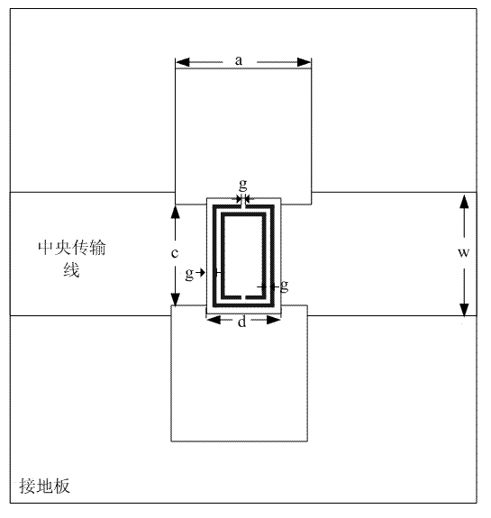
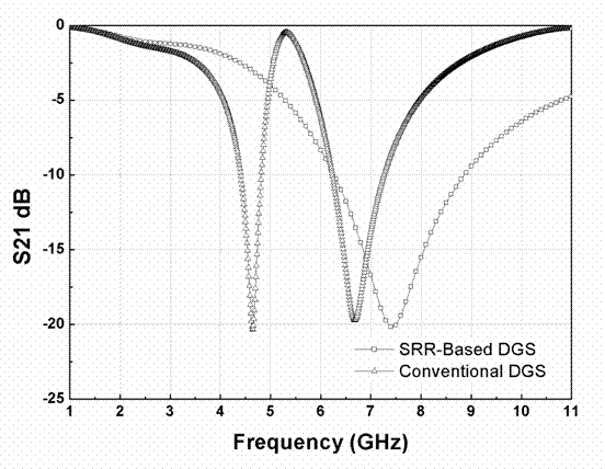
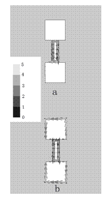
[0014] like figure 1 As shown, in a unit structure, a DGS (Defected Ground Structure) is etched on the ground plate, and a SRR (split-ring resonators) is added in the gap of the DGS. A dielectric plate with a dielectric constant of ε=2.6 is filled between the central transmission line and the ground plane. figure 2 It is a comparison of the S-parameter simulation results of this structure and only the DGS structure. Among them, the red line is the traditional DGS stopband filter, which has only one stopband and its center frequency is 7.43GHz. The blue line represents the S-parameter simulation results of this design. Has two stop bands. The center frequency of the first stop band is 4.64 GHz, and the center frequency of the second stop band is 6.68 GHz. image 3 is the surface current distribution diagram of the structure at 4.64GHz and 6.68GHz. from image 3 It can be seen that when the frequency is 4.64GHz, the current at the edge of DGS is obviously stronger than t...


PUM


Abstract

The invention discloses a miniature dual-stop band microstrip filter. A DGS is etched on an earth plate; an SRR is added into the gap of the DGS; and a dielectric slab with a dielectric constant epsilon of 2.6 is filled between a central transmission line and the earth plate. The invention is a planar microstrip dual-stop band filter, which has two stop bands of 3.62 GHz to 5.19 GHz and 6.13 GHz to 8.37 GHz. As the planar technology is adopted to arrange the SRR in the gap of the DGS, the size of the structure is very small compared with the traditional dual-stop band filter. The SRR is arranged in the gap of the DGS and two stop bands are generated as both of the SRR and the DGS have resonant effects. Moreover, due to the coupling effect of the SRR and the DGS, when the width of the gap of the DGS is increased, the central frequency of the two stop bands is reduced.

Description

technical field [0001] The invention relates to a miniaturized double-stop band microstrip line filter, which belongs to the technical field of microstrip line filters for microwave communication signal transmission. Background technique [0002] Existing dual stopband filters are generally large in size. The stopband filter based on the defective ground structure (Defected Ground Structure—DGS) generally has only one stopband, and the center frequency of the stopband will decrease as the width of the gap in the DGS in the structure increases. Contents of the invention [0003] The purpose of the present invention is to provide a miniaturized dual-stop band microstrip line filter for the defects of the prior art. A rectangular SRR (split ring resonators) structure is added to the gap of the DGS to realize two stop bands, and when When increasing the DGS slot width (since the SRR is located in the slot, the SRR and DGS slot widths increase at the same time), the center fre...

Claims


Application Information

Patent Timeline
Patent Type & Authority Patents(China)
IPC IPC(8): H01P1/203
Inventor 张雅男
Owner NANJING UNIV OF INFORMATION SCI & TECH
Why Eureka
Try Eureka