Digital delay phase locked loop circuit

A delay phase locked loop, digital delay line technology, applied in the direction of electrical components, automatic power control, etc., can solve the problem of slow locking speed, narrow applicable frequency, etc., to solve the problem of false lock, wide frequency range, and solve the problem of slow locking speed. Effect

Inactive Publication Date: 2011-01-19
SHANGHAI UNIVERSITY OF ELECTRIC POWER
View PDF4 Cites 29 Cited by
  • Summary
  • Abstract
  • Description
  • Claims
  • Application Information

AI Technical Summary

Problems solved by technology

[0008] The present invention aims at the problem that the applicable frequency of the current digital dela

Method used


Image

  • Digital delay phase locked loop circuit
  • Digital delay phase locked loop circuit
  • Digital delay phase locked loop circuit

Examples


Embodiment Construction

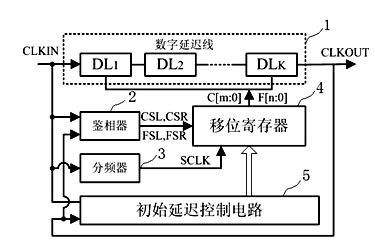
[0021] figure 2 is a digital delay-locked loop structure diagram, which is an improved register-controlled digital delay-locked loop, and the structure includes five functional modules: digital delay line 1, phase detector 2, clock divider 3, improved shifter Bit register 4, initial delay control circuit 5. The digital delay line 1 is composed of K (K is a natural number) identical delay units, each delay unit is controlled by the output signal of the improved shift register 4, and the phase detector 2 compares the input clock CLKIN with the delayed output clock CLKOUT Phase, before reaching a stable state, control the improved shift register 4 to shift left or right according to the phase comparison result, and the initial delay control circuit 5 measures the delay time from the input clock CLKIN to the output clock CLKOUT when starting up (using the input clock period The number indicates), so as to measure the initial condition of the system work, and then generate a set ...


PUM


Abstract

The invention relates to a digital delay phase locked loop circuit. In the circuit, a clock frequency divider and an initial delay control circuit are added; meanwhile, a shift register is improved; each delay unit of a digital delay line is controlled by an output signal of the improved shift register; a phase discriminator compares the phase of an input clock CLKIN and the phase of a delayed output clock CLKOUT; shift of the improved shift register is controlled according to a phase comparison result; the initial delay control circuit measures delay time from the input clock CLKIN to the output clock CLKOUT when started and then generates a setting signal to set the improved shift register; and the input clock CLKIN is output to serve as the input clock for the improved shift register after the frequency is divided by the clock frequency divider. The circuit solves the problems of slow locking speed and error locking of the conventional DLL structure, has a wider frequency range and is favorable for improving chip yield.

Description

technical field [0001] The invention relates to an integrated circuit, in particular to a digital delay phase-locked loop circuit. Background technique [0002] Phase-locked loop (PLL) and delay-locked loop (DLL) are currently widely used in microprocessors, memory interfaces, interfaces between chips, and clock distribution networks of large-scale integrated circuits to solve the clock skew problem, making The clock delay within the chip or between chips has enough margin, thus improving the timing function of the system. [0003] However, PLLs have stability and jitter (Jitter) issues that limit their use. For example, the bandwidth of the PLL loop is affected by changes in process, temperature, and voltage (PVT) conditions, resulting in system instability, and the voltage-controlled oscillator (VCO) will accumulate jitter, and because the output of the VCO will be fed back to the PLL, resulting in the previous Any uncertainty is passed on to the back. While the phase e...

Claims


Application Information

Patent Timeline
IPC IPC(8): H03L7/08
Inventor 叶波
Owner SHANGHAI UNIVERSITY OF ELECTRIC POWER
Why Eureka
Try Eureka