Longitudinal beam-free suspension frame with traction mechanisms on transverse beams

The technology of a traction mechanism and a suspension frame is applied in the field of suspension frames, which can solve the problems that the installation of maglev vehicles cannot be fully and effectively used, the cost of maintenance and repair is increased, the structure of the maglev vehicles is not compact enough, and the like. The effect of improving reliability and service life

Inactive Publication Date: 2011-01-26
TONGJI UNIV
View PDF5 Cites 19 Cited by
  • Summary
  • Abstract
  • Description
  • Claims
  • Application Information

AI Technical Summary

Problems solved by technology

[0006] 3. Since the longitudinal beam and traction mechanism are arranged in the middle of the suspension frame, it takes up a lot of space, making the structure of the suspension frame more complex, so that the structure of the entire magnetic levitation vehicle is not compact enough, and the space of the suspension frame cannot be fully an

Method used


Image

  • Longitudinal beam-free suspension frame with traction mechanisms on transverse beams
  • Longitudinal beam-free suspension frame with traction mechanisms on transverse beams
  • Longitudinal beam-free suspension frame with traction mechanisms on transverse beams

Examples


Embodiment Construction

[0036] based on the following Figure 2 ~ Figure 4 , to describe preferred embodiments of the present invention in detail.

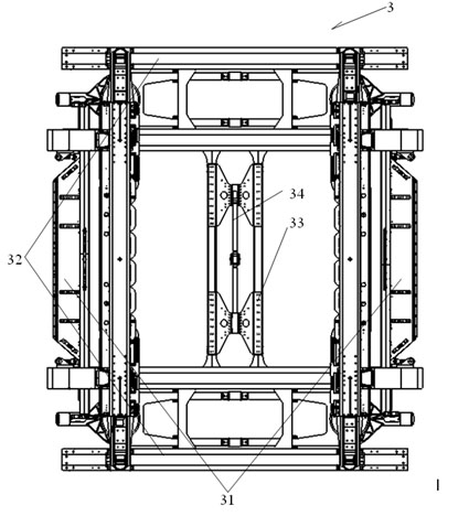
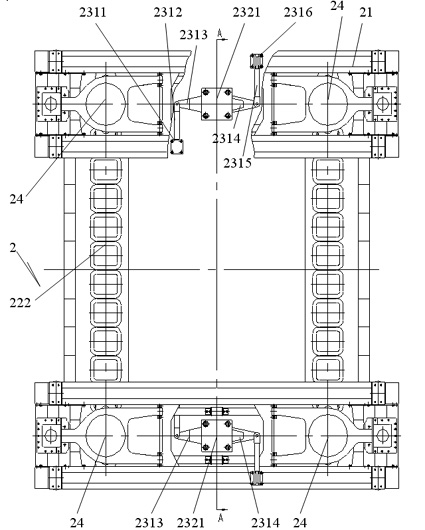
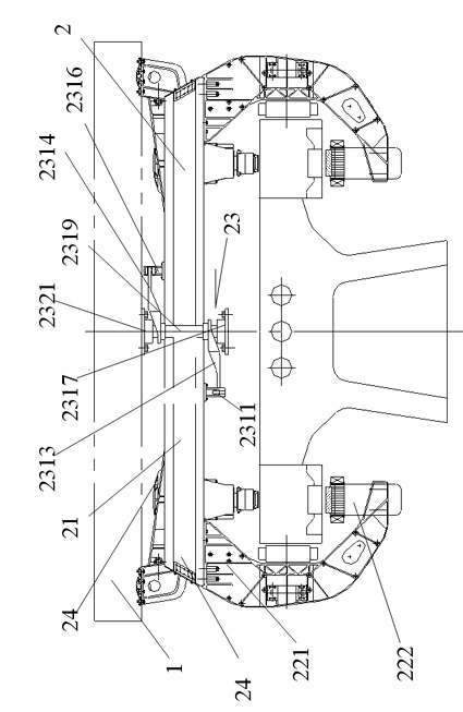
[0037] Such as Figure 2 ~ Figure 4 Shown is a front view, a top view, and a cross-sectional view of the front view along the A-A direction of a suspension frame provided by the present invention that has no longitudinal beam and is provided with a traction mechanism on the cross beam.

[0038] Such as figure 2 As shown, a suspension frame without a longitudinal beam and a traction mechanism on the cross beam described in this embodiment is arranged at the bottom of the vehicle body 1 (see image 3 ), including two sets of beams 21 , magnet modules 22 , traction mechanisms and bolsters 24 . Two groups of crossbeams 21 are arranged symmetrically, which are respectively connected with the vehicle body 1. The magnet modules 22 are arranged symmetrically at both ends of each group of crossbeams 21. A traction mechanism is arranged between each group of c...


PUM


Abstract

The invention relates to a longitudinal beam-free suspension frame with traction mechanisms on transverse beams. The suspension frame is arranged at the bottom of a vehicle body and comprises two groups of transverse beams, magnet modules and the traction mechanisms, wherein the two groups of transverse beams are arranged symmetrically and connected with the vehicle body through swing bolsters; the magnet modules are arranged symmetrically at the two ends of each group of transverse beams; and each group of transverse beams are provided with the traction mechanisms connected with the vehicle body and the transverse beams. The suspension frame has the advantages of eliminating the longitudinal beam of the suspension frame, simplifying structure, reducing weight, lowering manufacturing, maintenance and overhaul costs, preventing stress concentration at the joint between the longitudinal beam and the transverse beam when the suspension frame performs curve negotiating, enlarging the usable space in the suspension frame, releasing the restraint of the original longitudinal beam on radial rotation when a relevant transverse beam passes through a circular curve and relevant torsional restraint when the transverse beam passes through an easement curve, improving the motion decoupling of a corbel, balancing a series of spring stresses between an electromagnet and the corbel, reducing the disturbance of the bonding force of a walking mechanism on a suspension control system and contributing to the potential expression of a suspension guide control system.

Description

technical field [0001] The invention relates to a suspension frame, in particular to a suspension frame for a high-speed maglev vehicle without longitudinal beams and with traction mechanisms arranged on the cross beams. Background technique [0002] In the prior art, each compartment of a high-speed maglev vehicle is provided with four suspension frames. The main function of the suspension frame is to load electromagnets, motors, etc., and to transmit the suspension force, guiding force, traction force and braking force through the secondary suspension system. To the car body, while ensuring that the magnetic levitation car has the ability to pass through curves and ramps smoothly. Such as figure 1 as shown, figure 1 is a schematic diagram of a suspension frame with stringers in the prior art. Suspension frame 3 is made up of support arm group 31, beam group 32, longitudinal beam group 33 and traction mechanism 34. When the maglev vehicle passes through a curve or a ram...

Claims


Application Information

Patent Timeline
IPC IPC(8): B61B13/08B60L13/04
Inventor 高定刚胡杰罗世辉马卫华
Owner TONGJI UNIV
Why Eureka
Try Eureka