Wind magnet comprehensive generating system

A technology of power generation system and wind power generation device, which is applied in the direction of wind power engine, wind power motor combination, generator/motor, etc. It can solve the problems of no speed, increase of negative resistance, high cost, etc., and achieve the reduction of overall size and rotation resistance , Increase the effect of working ability

Active Publication Date: 2011-01-26
华丽联合高科技有限公司
View PDF7 Cites 7 Cited by
  • Summary
  • Abstract
  • Description
  • Claims
  • Application Information

AI Technical Summary

Problems solved by technology

Because the blades of the rotating wind wheel will generate half of the driving force and half of the resistance in the wind flow, therefore, in the case of strong winds, the speed of the rotating wind wheel increases, and the negative resistance generated by the rotating blades of the wind wheel increases, which ultimately reduces the power generation system. power generation efficiency
When the wind is small or there is no wind, the rotation speed of the rotating wind wheel is low or there is no rotation speed, so the power generation efficiency of the power generation system will also be reduced.
In order to improve the power generation efficiency of the power generation system, the general method is to increase the diameter of the wind wheel, so the existing rotating wind wheel is getting bigger and bigger. However, the larger the rotating wind wheel and the higher its height, the worse its stability. The higher the cost

Method used


Image

  • Wind magnet comprehensive generating system
  • Wind magnet comprehensive generating system
  • Wind magnet comprehensive generating system

Examples


Embodiment Construction

[0021] The present invention will be described in detail below in conjunction with the accompanying drawings and embodiments.

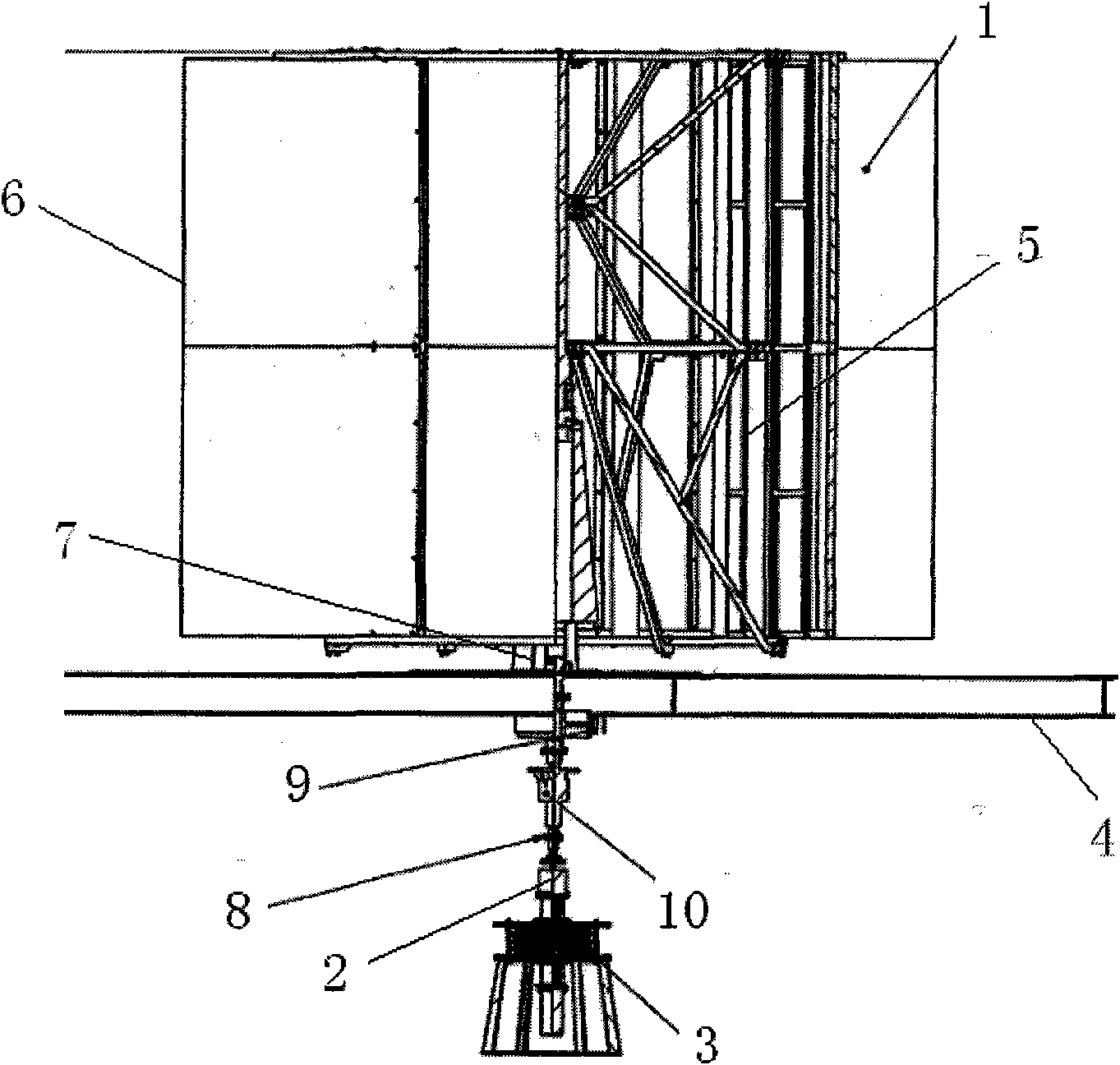
[0022] like figure 1 As shown, the present invention includes a wind power generator 1 , a generator 2 and a magnetodynamic generator 3 .

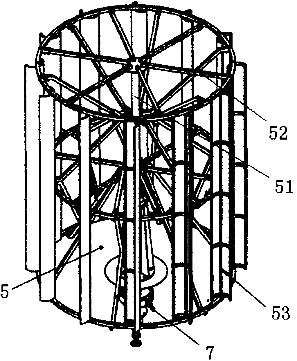
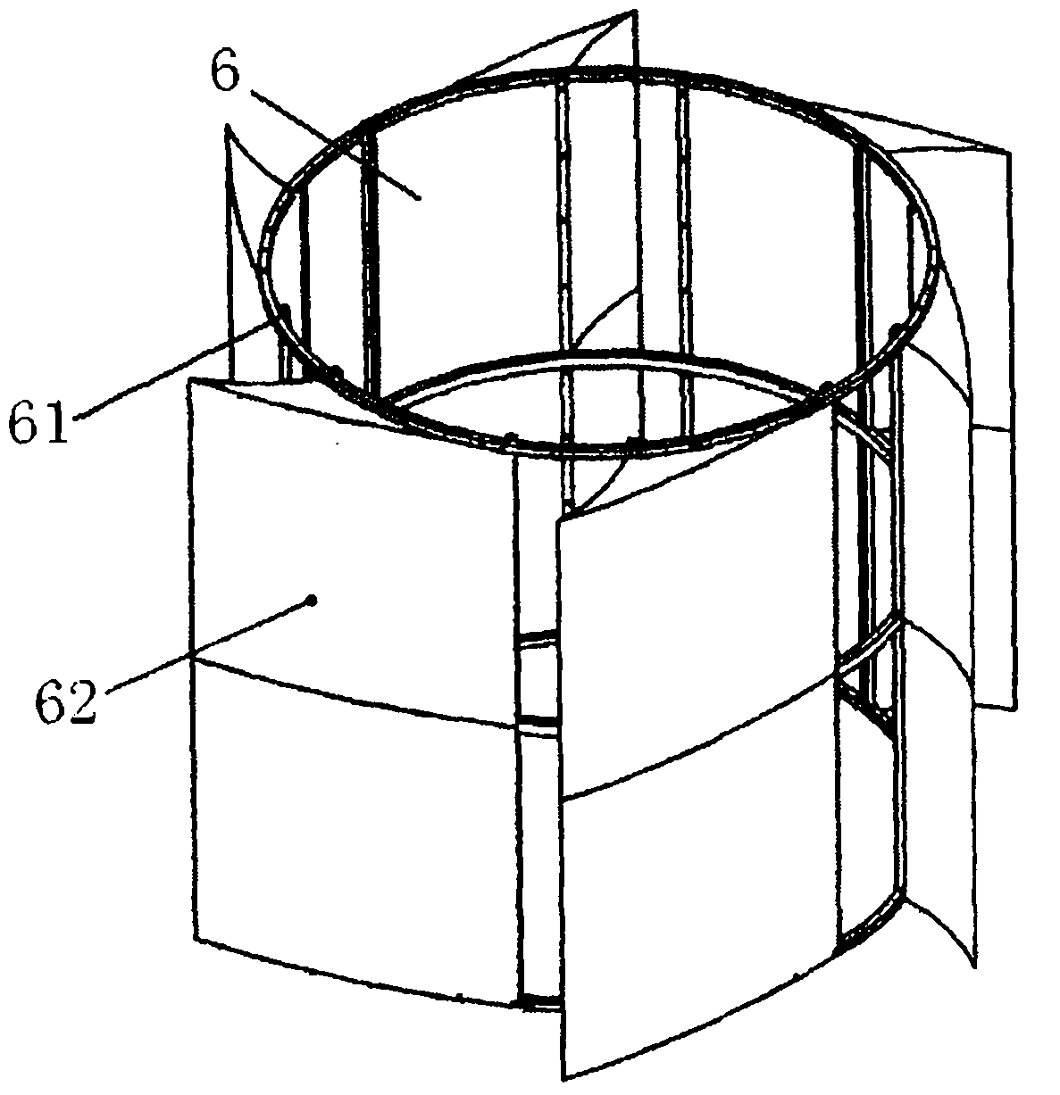
[0023] like figure 1 , figure 2 As shown, the wind power generation device 1 is arranged above the roof platform 4, and it includes a rotating wind wheel 5. The rotating wind wheel 5 includes a vertical main shaft 51, and the vertical main shaft 51 is provided with a circle of supporting frames 52 in the circumferential direction. Several fan blades 53 are provided. like figure 1 , image 3 , Figure 4 As shown, the periphery of the rotating wind wheel 5 is provided with a wind searching device 6 fixed on the roof installation platform 4, and the wind searching device 6 includes a wind searching barrel frame 61 in which the rotating wind wheel 5 can be installed, and the wind searching barrel frame 61 Ther...


PUM


Abstract

The invention relates to a wind magnet comprehensive generating system, which is characterized by comprising a wind power generation device which comprises a rotary wind power wheel; a wind searching barrel frame is arranged on the periphery of the rotary wind power wheel; 4-8 wind searching plates are arranged on the wind searching barrel frame at intervals; the cross section of the wind searching plate is in oblique triangle; a trumpet-shaped contraction air inlet channel is formed between the two adjacent wind searching plates; the upper end of the input shaft of the generator is connected with the output end of the rotary wind power wheel; the lower end of the input shaft of the generator is connected with a magnetic power generation device which comprises an upper flange plate and a lower flange plate; a generator baseplate fixed plate as a magnetic power working plate, a generator shaft rotary working plate, a generator shaft rotary working plate and a generator baseplate fixed plate are arranged between the upper flange plate and the lower flange plate in sequence; the generator baseplate fixed plate and the motor baseplate fixed plate are respectively fixed on the upper flange plate and the lower flange plate; the input shaft penetrates the generator baseplate fixed plate, and is connected with the generator shaft rotaty working pate; the center of the generator shaft rotary is fixed with a generator shaft; and the lower end of the generator shaft penetrates the lower flange plate and is connected with a low-voltage direct current generator.

Description

technical field [0001] The invention relates to a power generation system, in particular to a wind-magnetic integrated power generation system. Background technique [0002] Internationally, wind wheels are propelled by natural wind. Whether it is a three-blade vertical rotation or a horizontal rotation blade, it mainly relies on the tip of the outer edge to generate torque. Because the blades of the rotating wind wheel will generate half of the driving force and half of the resistance in the wind flow, therefore, in the case of strong winds, the speed of the rotating wind wheel increases, and the negative resistance generated by the rotating blades of the wind wheel increases, which ultimately reduces the power generation system. power generation efficiency. When the wind is small or there is no wind, the rotational speed of the rotating wind wheel is low or there is no rotational speed, so the power generation efficiency of the power generation system will also be reduced...

Claims


Application Information

Patent Timeline
Patent Type & Authority Applications(China)
IPC IPC(8): F03D9/00F03D3/00F03D3/04F03D3/06H02N11/00
CPCY02E10/74
Inventor 朱恒杰伍长序徐征
Owner 华丽联合高科技有限公司
Why Eureka
Try Eureka