Electric vehicle driving device
A driving device and electric car technology, applied in the direction of electric vehicles, electric braking systems, output power conversion devices, etc., to achieve the effect of stable communication
- Summary
- Abstract
- Description
- Claims
- Application Information
AI Technical Summary
Problems solved by technology
Method used
Image
Examples
Embodiment 1
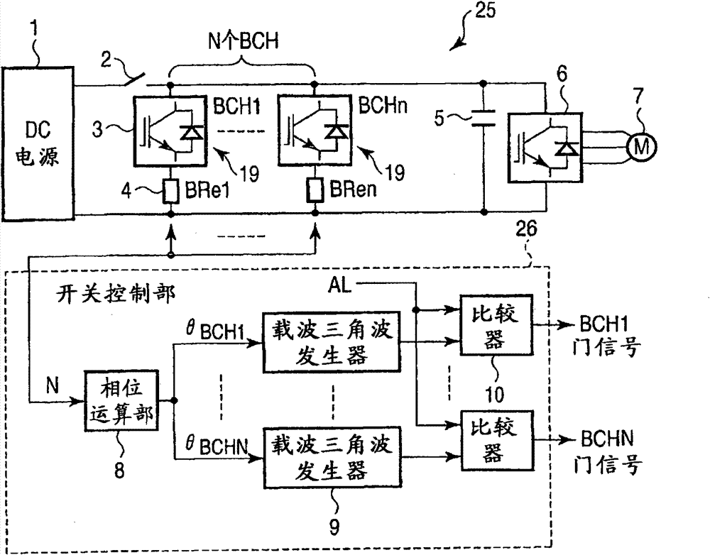
[0031] figure 1 It is a block diagram showing a schematic configuration of a first embodiment of the electric vehicle driving device of the present invention.
[0032] First, the main circuit 25 will be described. The DC power supply 1 is a direct current tram line (overhead), or an on-board engine generator+rectifier, or an AC tram line (overhead)+converter. The DC power source 1 is connected to a plurality of dynamic brakes 19 , a smoothing capacitor 5 and an inverter 6 through a first switch 2 . A motor 7 serving as a power source for driving the electric car is connected to the inverter 6 .
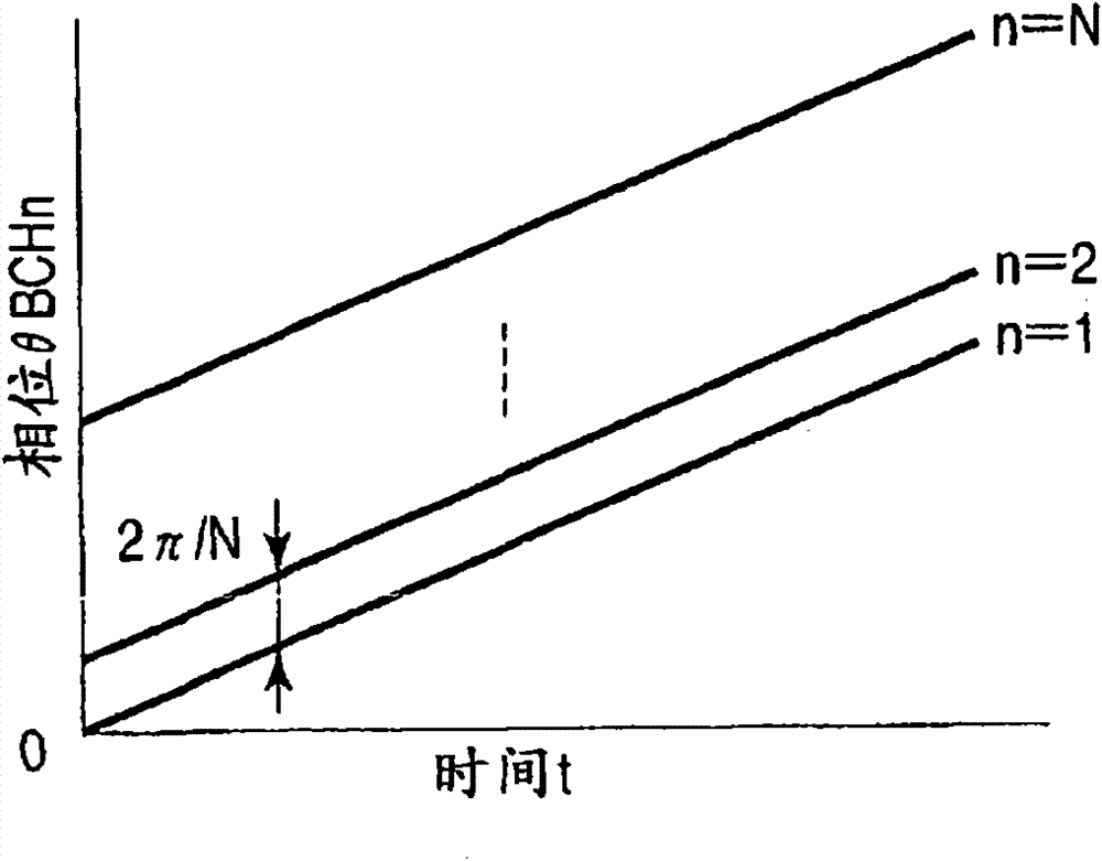
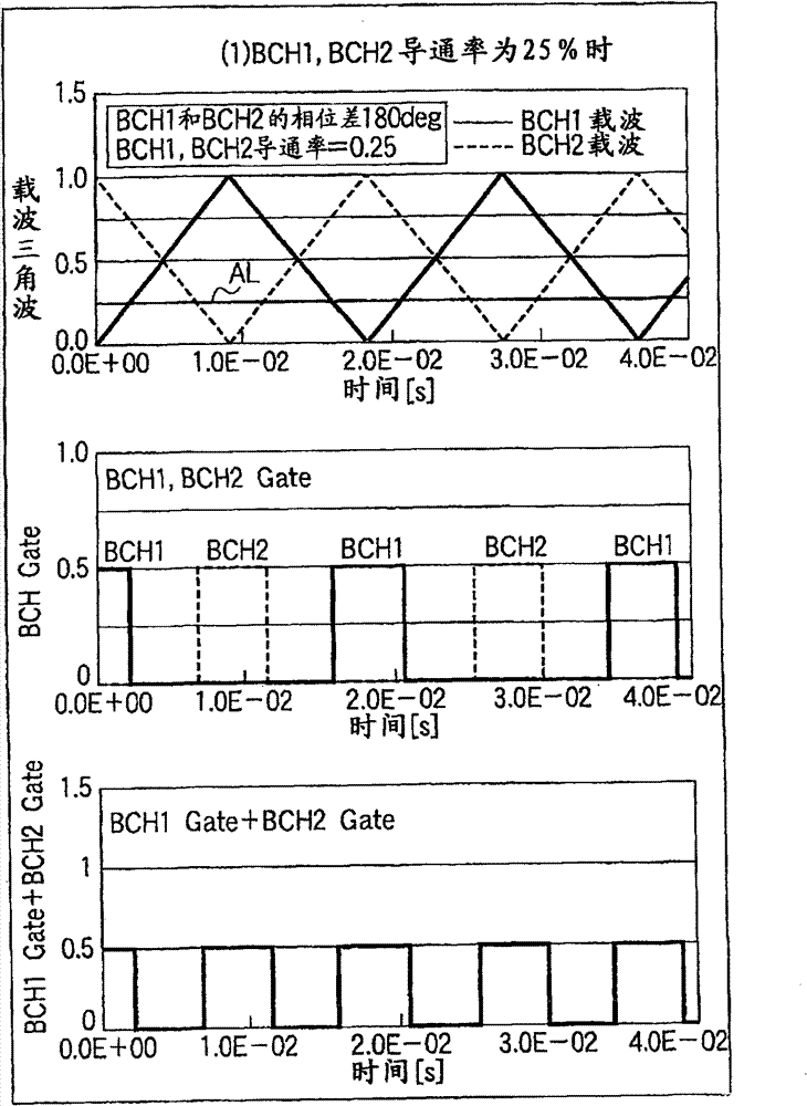
[0033] To both ends of the smoothing capacitor 5 , for example, N dynamic braking circuits 19 are connected in parallel. The generating brake circuit 19 is constituted as a series circuit of a brake chopper switch circuit 3 and a resistor 4 (hereinafter referred to as a brake resistor), wherein the brake chopper switch circuit 3 is used for controlling regenerative power, and the ...
Embodiment 2
[0047] Figure 5 It is a block diagram showing a schematic configuration of a second embodiment of the electric vehicle driving device of the present invention. The structure of the main circuit 25 is the same as that of the first embodiment. In the second embodiment, carrier triangle waves of different frequencies are supplied to the respective brake chopper switch circuits 3 of the switch control unit 26 .
[0048] The frequency calculation unit 11 provided in the switch control unit 26 receives the number N of brake chopper switch circuits 3 and calculates the frequency of the carrier triangular wave of each brake chopper switch circuit 3 . For example, the frequency fBCH of the carrier triangular wave is determined as in the following equation (2).
[0049] fBCHn=fO+(n-1)×Δf...(2)
[0050] Here, n represents the nth brake chopper switch circuit 3 (n=1 to N). N is the number of parallel brake chopper switch circuits 3 . Therefore, all the triangular carrier wave freque...
Embodiment 3
[0063] Image 6 It is a block diagram showing a schematic configuration of a third embodiment of the electric vehicle driving device of the present invention.
[0064] As usual, one dynamic braking circuit 19 is provided for one inverter circuit in the main circuit 25 . The switch control unit 26 includes a frequency calculation unit 12 , a carrier triangle wave generator 9 , a phase estimation unit 27 , and a comparator 10 . The phase estimation unit 27 receives the carrier triangular wave frequency fBCH from the frequency calculation unit 12, and calculates the phase θ (0° to 360°) of the triangular wave according to the following equation (4).
[0065] [mathematical formula 2]
[0066] θ=∫(2×π×fBCH)dt…(4)
[0067] The frequency calculating unit 12 calculates the carrier frequency fBCH based on the phase θ input from the phase estimating unit 27 . The carrier triangular wave generator 9 generates the carrier triangular wave of the brake chopper switching circuit 3 accord...
PUM
 Abstract
Description
Claims
Application Information
 - R&D
- Intellectual Property
- Life Sciences
- Materials
- Tech Scout
- Unparalleled Data Quality
- Higher Quality Content
- 60% Fewer Hallucinations
Browse by: Latest US Patents, China's latest patents, Technical Efficacy Thesaurus, Application Domain, Technology Topic, Popular Technical Reports.
© 2025 PatSnap. All rights reserved.Legal|Privacy policy|Modern Slavery Act Transparency Statement|Sitemap|About US| Contact US: help@patsnap.com


