Ring-die intelligent automatic cleaning plant
An automatic cleaning and ring die technology, applied in cleaning methods and utensils, cleaning methods using tools, chemical instruments and methods, etc., can solve problems such as low cleaning efficiency, worker fatigue, misoperation, etc., to reduce labor intensity, ensure The effect of cleaning quality and improving cleaning efficiency
- Summary
- Abstract
- Description
- Claims
- Application Information
AI Technical Summary
Problems solved by technology
Method used
Image

Examples
Embodiment Construction
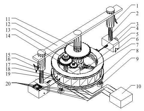
[0016] refer to figure 1 . It is connected with the bracket system and drives the bracket system to rotate. The ring mold intelligent automatic cleaning system is installed on the bracket system, facing the ring mold, and the control lines of the control system are respectively connected with the gear transmission system and the motor of the ring membrane intelligent automatic cleaning system.
[0017] The support system consists of main support 11, beam 12, left support 15, right support 2, first adjustment handle 1, second adjustment handle 6, third adjustment handle 16, support frame 9, pin 5 and workpiece holder 7 components, the main bracket 11 is affixed to the center of the beam 12, the left bracket 15, the right bracket 2 are affixed to the two ends of the beam 12, the first adjustment handle 1, the second adjustment handle 6, and the third adjustment handle 16 are arranged on the left On the support 15 and the right support 2, the support frame 9, the pin 5 and the w...
PUM
 Abstract
Description
Claims
Application Information
 - Generate Ideas
- Intellectual Property
- Life Sciences
- Materials
- Tech Scout
- Unparalleled Data Quality
- Higher Quality Content
- 60% Fewer Hallucinations
Browse by: Latest US Patents, China's latest patents, Technical Efficacy Thesaurus, Application Domain, Technology Topic, Popular Technical Reports.
© 2025 PatSnap. All rights reserved.Legal|Privacy policy|Modern Slavery Act Transparency Statement|Sitemap|About US| Contact US: help@patsnap.com