Water surface floating oil recovery ship

A technology for oil slicks on the water surface and recovery ships, which is applied to special-purpose ships, ships, motor vehicles, etc. It can solve the problems of oil slick viscosity requirements, easy to cause blockage, and poor effect, so as to improve the oil sweeping surface and reduce emulsification High efficiency and wide application range

Inactive Publication Date: 2011-02-02
宁波市科技园区海星船舶设计所
View PDF8 Cites 20 Cited by
  • Summary
  • Abstract
  • Description
  • Claims
  • Application Information

AI Technical Summary

Problems solved by technology

When recovering oil spills, turn on the diversion pump, and the water surface will generate guiding water flow to offset the influence of the bow wave, and quickly lead the spilled oil to the oil collection zone. The oil leaks out of the grid, and the oil adheres to the oil recovery belt, which greatly improves the recovery rate of the spilled oil. However, due to the use of the oil recovery belt to collect oil, there is a requirement for the viscosity of the slick oil. For those thinner oil slicks, use the oil recovery belt The effect of collecting oil is not good, and the oil sweeping surface is relatively small
[0004] In addition, a Chinese utility model patent specification with the application date of August 22, 2008 and the patent number ZL200820135352.8 discloses a water surface oil slick recovery device, which is applied to the water surface oil slick recovery operation. Plates, conical tubes, side plates and bottom plates

Method used


Image

  • Water surface floating oil recovery ship
  • Water surface floating oil recovery ship
  • Water surface floating oil recovery ship

Examples


Embodiment Construction

[0019] The present invention will be further described in detail below in conjunction with the accompanying drawings and embodiments.

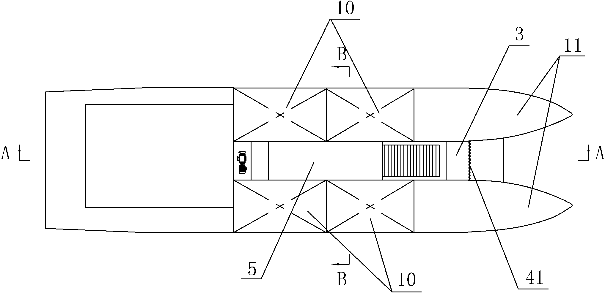
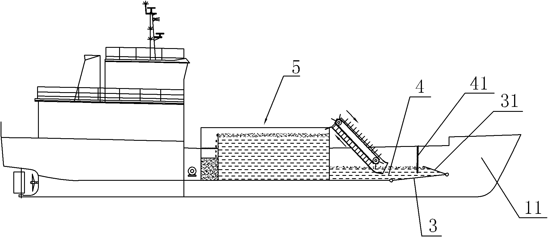
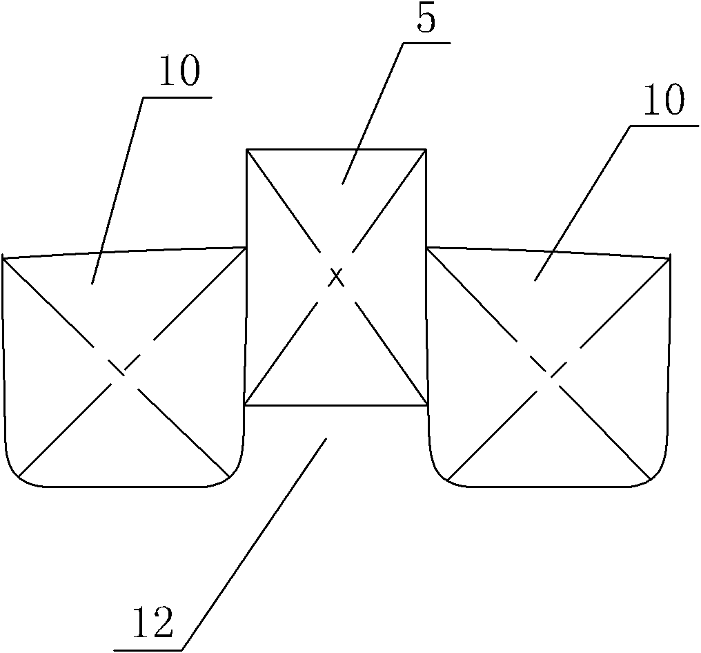
[0020] As shown in the figure, a surface oil slick recovery ship includes a hull, an oil slick collection device, and an oil-water separation device 5. The oil-water separation device 5 includes an oil-water separation bin 51 and an oil collection bin 52. The bow 11 of the hull is a catamaran structure, the bow 11 is in the shape of a sharp cone, the middle part of the hull to the stern is a monohull structure, and the bottom of the monohull structure part is provided with an inwardly concave longitudinal diversion channel 12, and the floating oil collection device includes a chain type The oil slick lifting device and the oil water pool 4 arranged in the middle of the hull, the water inlet of the oil water pool 4 is hinged with a water inlet baffle 3, the water inlet baffle 3 is located in the middle of the catamaran structural part, the water...


PUM


Abstract

The invention discloses a water surface floating oil recovery ship. The water surface floating oil recovery ship comprises a hull, a floating oil collecting device and an oil and water separating device, and is characterized in that: the stem of the hull has a catamaran structure and is in a pointed cone form; the middle part to the tail part of the hull has a single hull structure; and a flow guiding channel which is recessed inward and is through in the longitudinal direction is formed in the middle of the bottom of the part which has the single hull structure. The water surface floating oil recovery ship has the advantages that: because the stem of the hull has the catamaran structure, and the flow guiding channel which is recessed inward and is through in the longitudinal direction isformed in the middle of the bottom of the part which has the single hull structure, the oil intake resistance generated in the driving process of the ship can be greatly reduced, floating oil can smoothly enter an oil and water pool, and the oil sweeping area of the ship is increased; and due to a chain type floating oil lifting device, a floating oil heating device in an oil and water separatingcabin, and two garbage filtering grids which are additionally arranged, the overall floating oil recovery ship can be applied to the floating oil with any viscosity and any thickness and has low requirements on a water surface environment, and the applicable water area is wide.

Description

technical field [0001] The invention relates to a surface oil recovery ship. Background technique [0002] Since the last century, with the wide application of petroleum products, the problem of oil pollution in oceans and rivers has become increasingly serious. The most important problem is the discharge and leakage of petroleum and its products, which seriously damages the environment and ecology of polluted waters and their coastlines. balance. In order to recover the oil slick on the water surface, many countries have invested in the research and development of oil spill emergency recovery technology, and the oil slick recovery ship is the most important equipment in this field. [0003] The application date is November 11, 2000, and the Chinese utility model patent specification No. ZL00256382.7 discloses an oil slick recovery ship, which includes a hull and an oil skimmer, and is characterized in that: the front deck of the hull has a groove, The front end of the u...

Claims


Application Information

Patent Timeline
IPC IPC(8): B63B35/32
Inventor 胡建平黄刚徐明高兆进
Owner 宁波市科技园区海星船舶设计所
Why Eureka
Try Eureka