
Device and method for measuring physical parameters of aeolotropic substance

An anisotropic, material technology, applied in the field of heterodyne interferometry of physical parameters, can solve the problems of low accuracy, trouble, inability to measure the physical parameters of anisotropic materials, etc., to achieve stable measurement values ​​and reduce environmental interference. Effect

Inactive Publication Date: 2011-02-02
HANNSTAR DISPLAY CORPORATION
View PDF1 Cites 13 Cited by
  • Summary
  • Abstract
  • Description
  • Claims
  • Application Information

AI Technical Summary

Problems solved by technology

[0005] (3) The analysis of interference patterns is also more complex, troublesome and less accurate
[0008] However, the method disclosed in US Patent No. 5,946,096 can only measure the physical parameters of isotropic substances, but cannot measure the physical parameters of anisotropic substances

Method used


Image

  • Device and method for measuring physical parameters of aeolotropic substance
  • Device and method for measuring physical parameters of aeolotropic substance
  • Device and method for measuring physical parameters of aeolotropic substance

Examples


Embodiment Construction

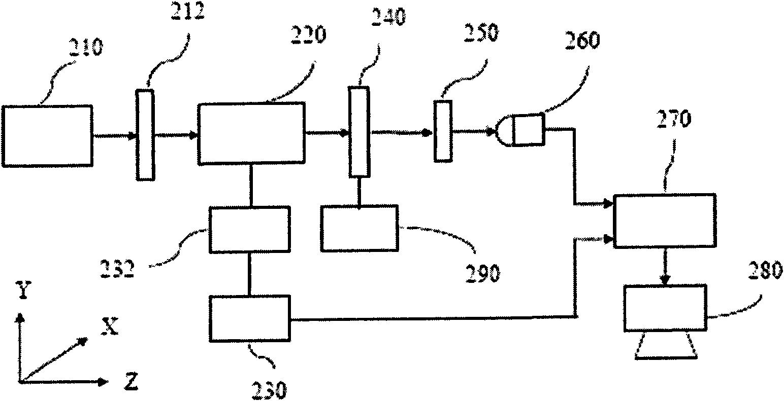
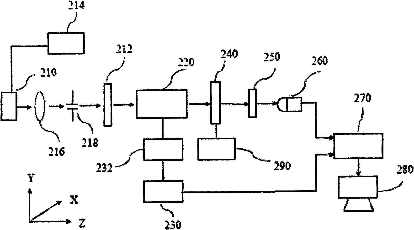
[0021] refer to figure 2 The device for measuring the physical parameters of anisotropic material (anisotropic material) using transmission heterodyne interferometry according to the first embodiment of the present invention includes a light source 210, such as a laser, such as a gas laser, such as a helium-neon laser, using to produce highly polarized light beams. The light beam emitted by the light source 210 can optionally pass through the linearly polarized polarizer 212 to obtain a light beam with a higher degree of polarization. The light beam then passes through the electro-optic modulator 220 , which is connected to, driven and controlled by a driver 232 . The driver 232 is also connected to the signal generator 230 so that the electro-optic modulator 220 can be driven by the driver 232 according to a desired mode, so as to modulate the beam passing through the electro-optic modulator 220 to generate a desired heterodyne beam. In addition, the signal generator 230 a...


PUM


Abstract

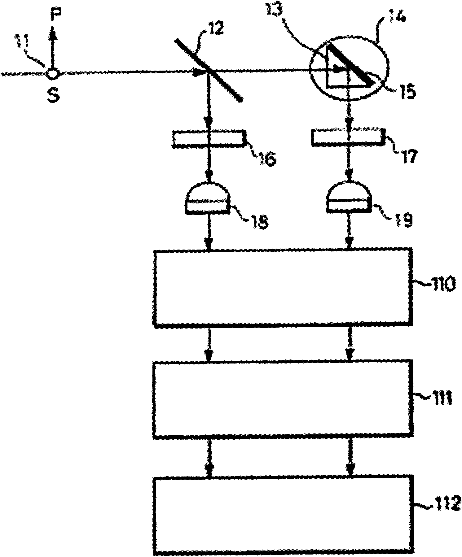
The invention provides a method and a device for measuring the physical parameters of an aeolotropic substance by using the transmission type heterodyne interferometry. Two mutually orthogonal polarized light beams with slightly different frequencies pass through the aeolotropic substance to be measured, and interference is produced through an analyzer with linear polarization. An optical detector is used for detecting the interfered light and converting the interfered light into an interference signal, and a phasometer or a locking amplifier is used for acquiring the phase difference between the interference signal and a reference signal.

Description

technical field [0001] The invention relates to a common optical path heterodyne interferometry, more particularly to a heterodyne interferometry for measuring physical parameters of anisotropic substances. Background technique [0002] There are many types of interferometry and interferometers used for optical and non-contact measurements, but most of the interferometry or interferometers are not in a common optical path structure. In general, non-co-optics structures have the following problems: [0003] (1) In the non-common optical path structure, the optical path difference between the reference beam and the test beam must be within the coherence length. Furthermore, as the optical path difference increases, the contrast of the interference signal will decrease. [0004] (2) In the non-common optical path structure, the environment of the two beams should be strictly controlled. For example, air turbulence and external vibrations should be avoided. In addition, the ...

Claims


Application Information

Patent Timeline
Patent Type & Authority Applications(China)
IPC IPC(8): G01D5/26G02F1/13G01B11/06G01B11/26
Inventor 曾恒正李瑞斌陈威州
Owner HANNSTAR DISPLAY CORPORATION
Learn More