Liquid crystal display driving device

A driving device and liquid crystal display technology, applied in the field of liquid crystal display driving and liquid crystal display driving device, can solve the problems of display screen flickering and the quality of the display screen cannot meet the requirements, so as to reduce the impact, ensure the charging rate, and meet the charging time. Effect

Active Publication Date: 2011-02-02
BEIJING BOE OPTOELECTRONCIS TECH CO LTD
View PDF0 Cites 33 Cited by
  • Summary
  • Abstract
  • Description
  • Claims
  • Application Information

AI Technical Summary

Problems solved by technology

[0007] The object of the present invention is to provide a liquid crystal display driving device to improve the quality of the display picture and the flickering phenomenon of t...

Method used


Image

  • Liquid crystal display driving device
  • Liquid crystal display driving device
  • Liquid crystal display driving device

Examples


Embodiment Construction

[0027] The present invention will be described in further detail below through specific embodiments and in conjunction with the accompanying drawings.

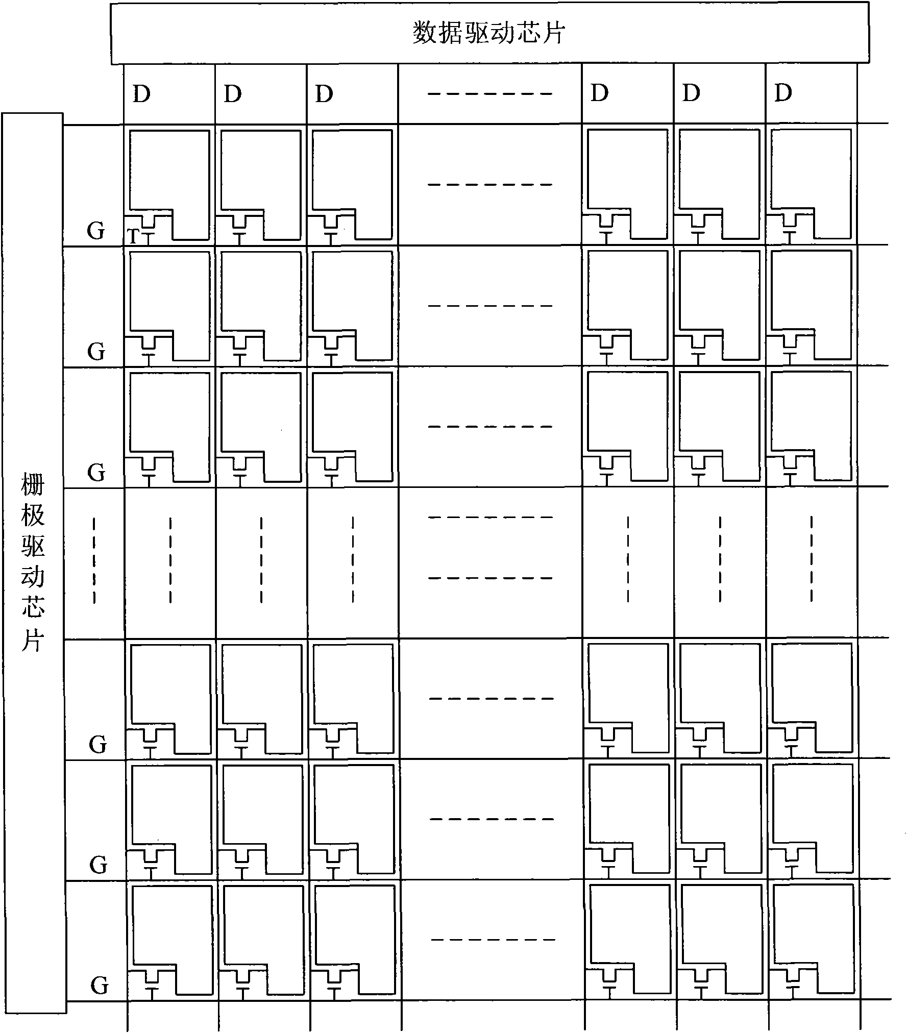
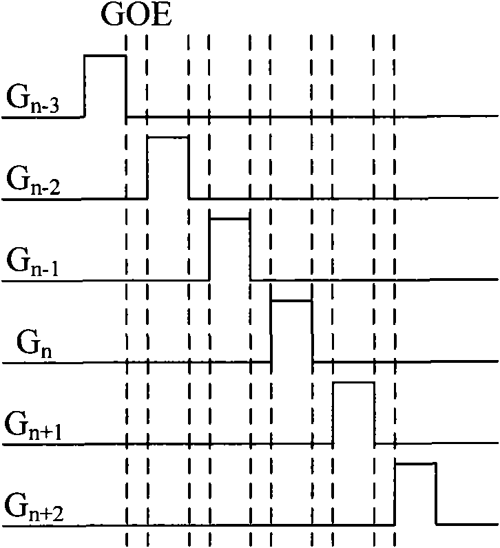
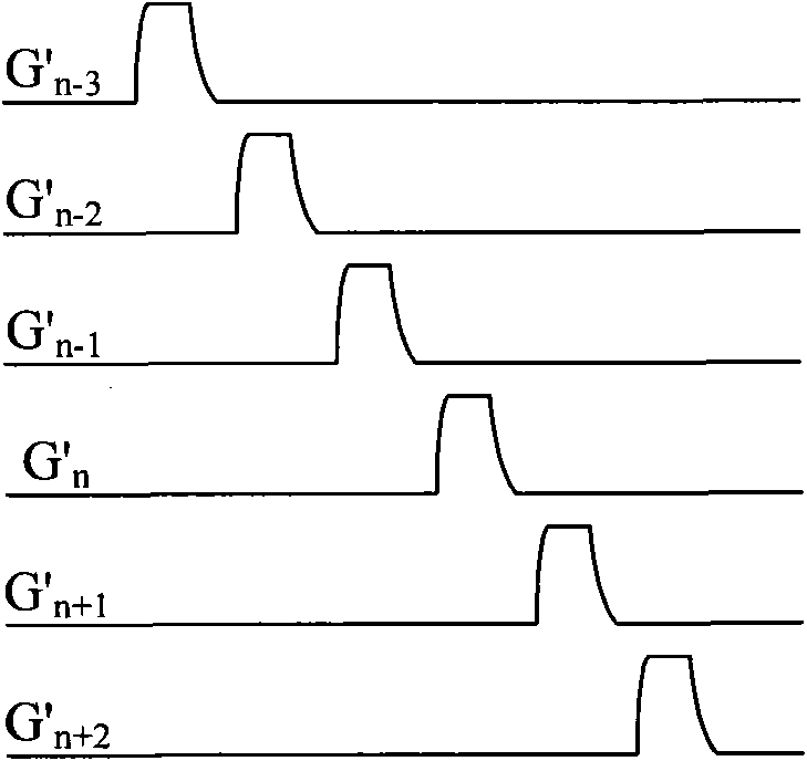
[0028] An embodiment of the present invention provides a liquid crystal display drive device, including a scan drive unit, a data drive unit, a gate line, a data line, and a pixel area formed by the gate line and the data line, wherein the gate line includes a gate scan line and a redundant gate line , the data line includes a data signal line and a redundant data line, and the liquid crystal display driving device also includes: a compensation circuit connected to the gate line, used to compensate the gate scan signal on the gate scan line, and improve the grid Voltage delay phenomenon on scan lines. The embodiment of the present invention is mainly generated by connecting a compensation circuit at the end of the gate line to compensate the gate scan signal to reduce the impact on the rise time and / or fall time of the gate sc...


PUM


Abstract

The invention relates to a liquid crystal display driving device. The liquid crystal display driving device comprises a scan driving unit, a data driving unit, a grid line, a data line and a pixel region which is formed by the grid line and the data line, wherein the grid line comprises a grid scanning line and a redundant grid line; the data line comprises a data signal wire and a redundant data line; and the liquid crystal display driving device also comprises a compensating circuit which is connected with the grid line for compensating a grid scanning signal on the grid scanning line to improve voltage delay phenomenon on the grid scanning line. The liquid crystal display driving device provided by the invention can compensate the grid scanning signal through the compensating circuit which is connected with the grid line, so that the influence of overtime of resistance-capacitance (RC) on the rise time and/or the fall time of the grid scanning signal can be reduced, the charging time requirement of a pixel can be fully met, and the charging rate of the pixel is ensured.

Description

technical field [0001] The invention relates to driving of liquid crystal display, in particular to a driving device of liquid crystal display, which belongs to the field of driving of liquid crystal display. Background technique [0002] At present, the thin film transistor liquid crystal display (TFT-LCD) has become the most important type of display in the display, and the development direction of the TFT-LCD is even more towards the direction of large size and high resolution. However, as the size of the TFT-LCD increases, the gate scanning lines and data signal lines in the TFT-LCD will become longer, which will inevitably lead to an increasing resistance of the gate scanning lines and data signal lines; The higher the resolution, the more overlapping areas between the gate scanning lines and the data signal lines, which will increase the parasitic capacitance of each signal line. [0003] figure 1 It is a structural schematic diagram of an existing TFT liquid crystal...

Claims


Application Information

Patent Timeline
IPC IPC(8): G02F1/1362
CPCG09G3/3677G02F1/136286G09G2300/043G09G2320/0219G09G3/3674G09G3/3648
Inventor 胡明车春城
Owner BEIJING BOE OPTOELECTRONCIS TECH CO LTD
Why Eureka
Try Eureka