LED control circuit

A technology for controlling circuits and charging circuits, which is applied to the layout of electric lamp circuits, electric light sources, lighting devices, etc., and can solve problems such as limited improvement effects, reduced system efficiency, and large delays in control circuits

Inactive Publication Date: 2011-02-02
金峰
View PDF5 Cites 16 Cited by
  • Summary
  • Abstract
  • Description
  • Claims
  • Application Information

AI Technical Summary

Problems solved by technology

Existing technologies such as figure 2 As shown, the delay of the control circuit in the traditional implementation is relatively large, and its delay time is limited by the speed of the operational amplifier OP3
Increasing the operating current of the operational amplifier OP3 can reduce the delay time, but the improvement effect is very limited
In addition, the operating current of OP3 should not be increased too much, otherwise it will consume more power and reduce system efficiency

Method used


Image

  • LED control circuit
  • LED control circuit
  • LED control circuit

Examples


Embodiment Construction

[0033] The implementation of the present invention will be described in detail below in conjunction with the drawings and examples, so that the realization process of how to use technical means to solve technical problems and achieve technical effects in the present invention can be fully understood and implemented accordingly.
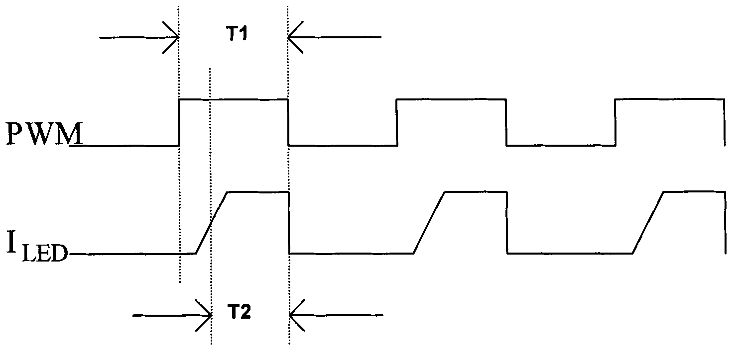
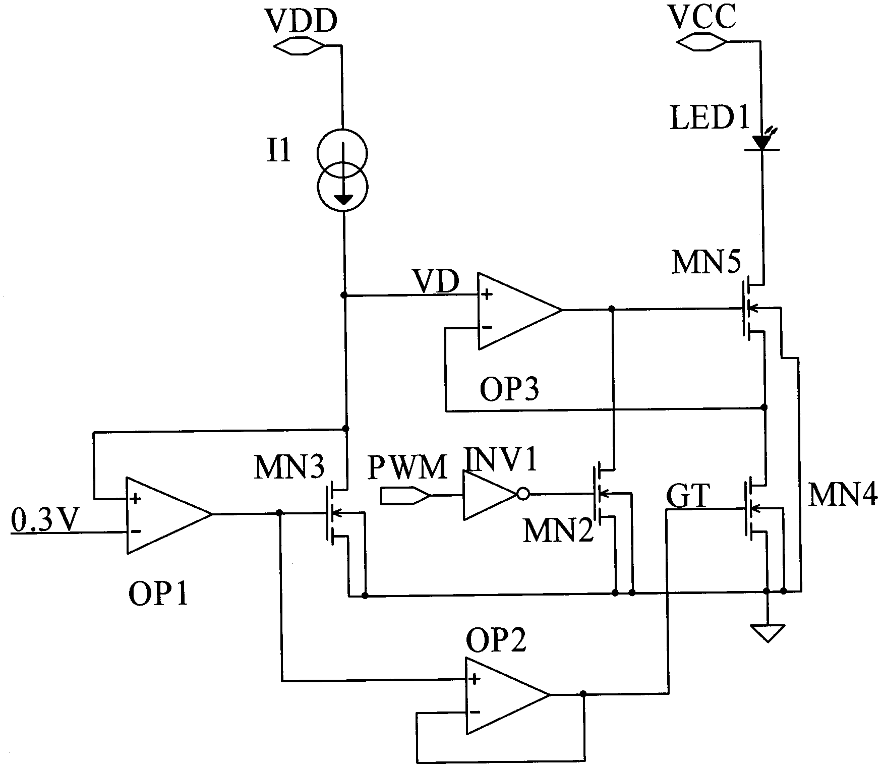
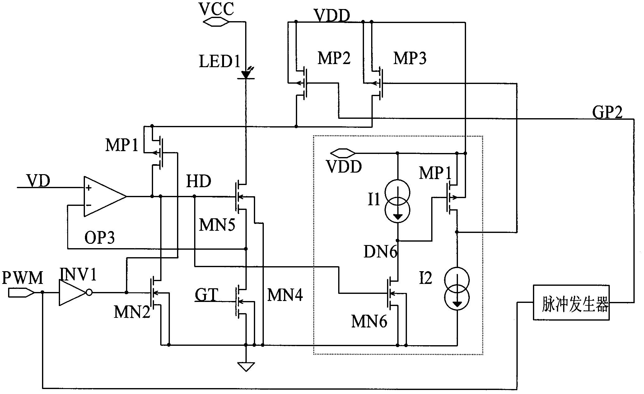
[0034] The core idea of ​​the present invention is: by adding a charging acceleration circuit A, triggered by the PWM signal, it is kept on during the period when the LED current output is enabled until the LED current starts to rise, and the current is input to the charging circuit A. The circuit makes it quickly pass the threshold voltage to enter the conduction state; also by adding a charging acceleration circuit B (the relevant circuit of MP4 in the application example below), it starts when the charging circuit is turned on, and when the LED current starts to rise to The LED current is kept on during the period of outputting the target current va...


PUM


Abstract

The invention discloses a light emitting diode (LED) control circuit. The LED control circuit comprises a drive circuit, a charging circuit and an LED which are connected in turn, wherein the drive circuit is started by a pulse width modulation (PWM) signal; the drive circuit enables the charging circuit to output an LED current to the LED; and after the charging circuit is on, the LED circuit rises. The LED control circuit also comprises a charging accelerating circuit A, wherein the charging accelerating circuit A is triggered and started by the PWM signal, keeps conduction in a period that the LED current is output till the LED current starts to rise, and generates a current input to the charging circuit to ensure that the charging circuit quickly reaches a threshold value voltage to enter a conducting state. The LED control circuit has the advantages of obviously shortening current output delay time, improving the response speed of a system, effectively controlling LED current overshoot not to happen at an LED current advancing edge, and improving the linearity of brightness control of the LED in a PMW current regulation mode.

Description

technical field [0001] The invention belongs to the field of control circuits, in particular to an LED control circuit for accelerating the response speed of LED current output. Background technique [0002] LED (light-emitting diode) large-screen billboards are usually realized by a dot matrix composed of many LEDs. Each LED needs to be driven by the LED control circuit. Generally, the LED control circuit needs to output a constant current to ensure the brightness consistency and color accuracy of the LED light. The deviation of LED current will directly affect the color and brightness of its light. Usually, in addition to ensuring accurate LED current control, it is also necessary to achieve linear adjustment of LED brightness by controlling the duty cycle of the driving LED current. The conventional adjustment method is to control the lighting and closing of the LED through the pulse width modulation (PWM) signal. For example, the pulse width modulation signal is a peri...

Claims


Application Information

Patent Timeline
IPC IPC(8): H05B37/02G09G3/32
Inventor 王钊金峰
Owner 金峰
Why Eureka
Try Eureka