Method for producing a 2D collimator element and 2D collimator element

A collimator and component technology, applied in the direction of using aperture/collimator, instruments, scientific instruments, etc., can solve the problems of reducing the collimation effect of spacers, and achieve the goal of simplifying expenses, reducing cost expenses, and reducing component weight Effect

Inactive Publication Date: 2011-02-02
SIEMENS AG
View PDF6 Cites 29 Cited by
  • Summary
  • Abstract
  • Description
  • Claims
  • Application Information

AI Technical Summary

Problems solved by technology

However, this has the disadvantage that the collimation effect of the constructed spacers is ...

Method used


Image

  • Method for producing a 2D collimator element and 2D collimator element
  • Method for producing a 2D collimator element and 2D collimator element
  • Method for producing a 2D collimator element and 2D collimator element

Examples


Embodiment Construction

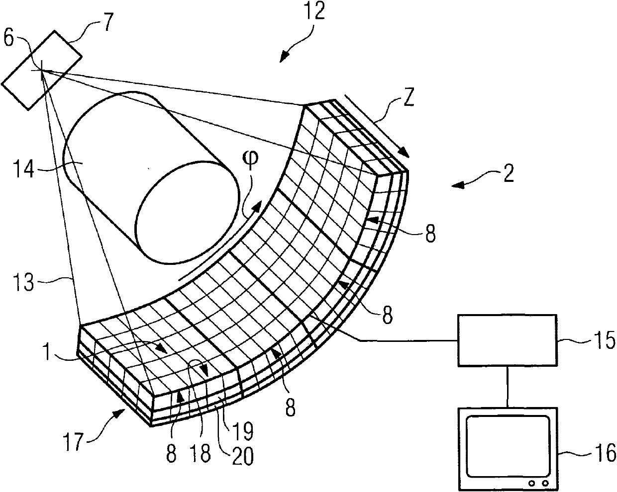
[0031] figure 1 A computed tomography system 12 is shown, which comprises a radiation source in the form of an x-ray tube 7 , from whose focal point a fan-shaped x-ray 13 is emitted. The fan-shaped x-rays 13 penetrate the object 14 to be examined or the patient and emerge at a radiation detector, here the x-ray detector 2 .

[0032] The x-ray tube 7 and the x-ray detector 2 are arranged opposite each other on a gantry of a computed tomography system 12 (not shown here), which surrounds the system axis z (=patient axis) of the computed tomography system 2 )exist direction is rotatable. which is, The direction indicates the circumferential direction of the gantry and the z-axis indicates the longitudinal axis of the object 14 to be examined.

[0033] During operation of the computed tomography system 2 , the x-ray tube 7 and the x-ray detector 2 arranged on a gantry rotate around the object 14 , wherein x-ray images of the object 14 are acquired from different projection d...


PUM


Abstract

A method is disclosed for producing a 2D collimator element for a radiation detector, in which crossing webs made of a radiation-absorbing material are formed, layer-by-layer, by way of a rapid manufacturing technique. In at least one embodiment, the webs are aligned along a [phi]- and a z-direction and form a cell-shaped structure with laterally enclosed radiation channels, at least in the inner region of the 2D collimator element. In at least one embodiment, the invention moreover relates to a 2D collimator element for a radiation detector that has such a layered construction. This allows the provision of a very precise and rigid collimator arrangement which, at the same time, has a high collimation effect.

Description

technical field [0001] The invention relates to a method for producing a two-dimensional collimator element for a radiation detector and to a two-dimensional collimator element. Background technique [0002] For example, collimators are used in imaging with x-ray devices, such as computed tomography devices for examining patients. The computed tomography system has an x-ray system arranged on a gantry with an x-ray source and an x-ray detector. Typically, an x-ray detector is constructed from a plurality of detector modules arranged linearly or two-dimensionally with one another. Each detector module of the X-ray detector comprises, for example, an array of scintillation crystals and an array of photodiodes aligned with each other. The mutually aligned elements of the scintillation crystal array and the photodiode array form the detector elements of the detector module. X-rays incident on the array of scintillation crystals are converted into light, which is converted int...

Claims


Application Information

Patent Timeline
IPC IPC(8): G21K1/02
CPCG21K1/025G01T1/2985Y10T29/49002B33Y80/00B33Y70/00
Inventor 马里奥·艾肯希尔迈克尔·梅斯丹尼尔·尼德洛纳斯蒂芬·沃思
Owner SIEMENS AG
Why Eureka
Try Eureka