Steel wire cutter of steel wire ring

A technology of steel traveler and steel wire, which is applied to tires, manufacturing rings by wire, and other household appliances, etc., can solve the problems of time-consuming, labor-intensive, cost-increasing, and low utilization of equipment, so as to reduce costs, reduce workload, and shorten production cycles. Effect

Inactive Publication Date: 2011-02-09
HAOHUA SOUTH CHINAGUILIN RUBBER
View PDF4 Cites 0 Cited by
  • Summary
  • Abstract
  • Description
  • Claims
  • Application Information

AI Technical Summary

Problems solved by technology

This operation is not only time-consuming and labor-intensive, but also increases costs, and the utilization rate of equipment is also low.

Method used


Image

  • Steel wire cutter of steel wire ring
  • Steel wire cutter of steel wire ring
  • Steel wire cutter of steel wire ring

Examples


Embodiment Construction

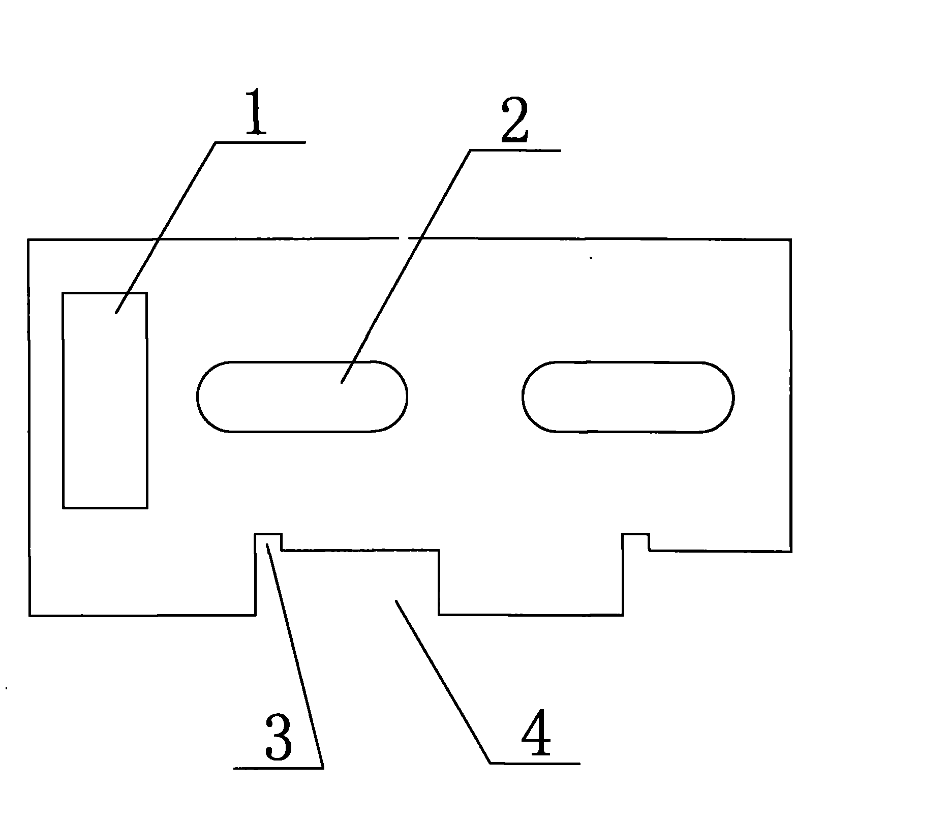
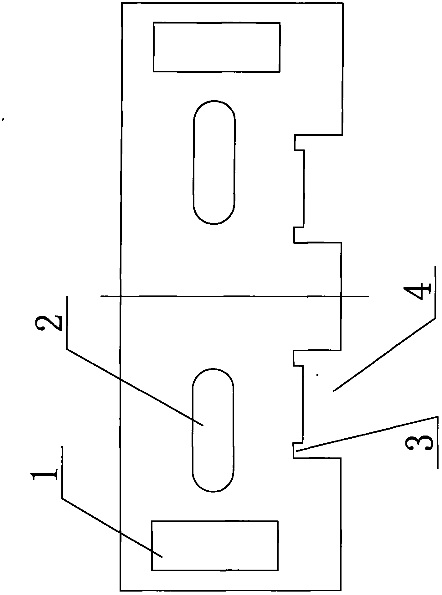
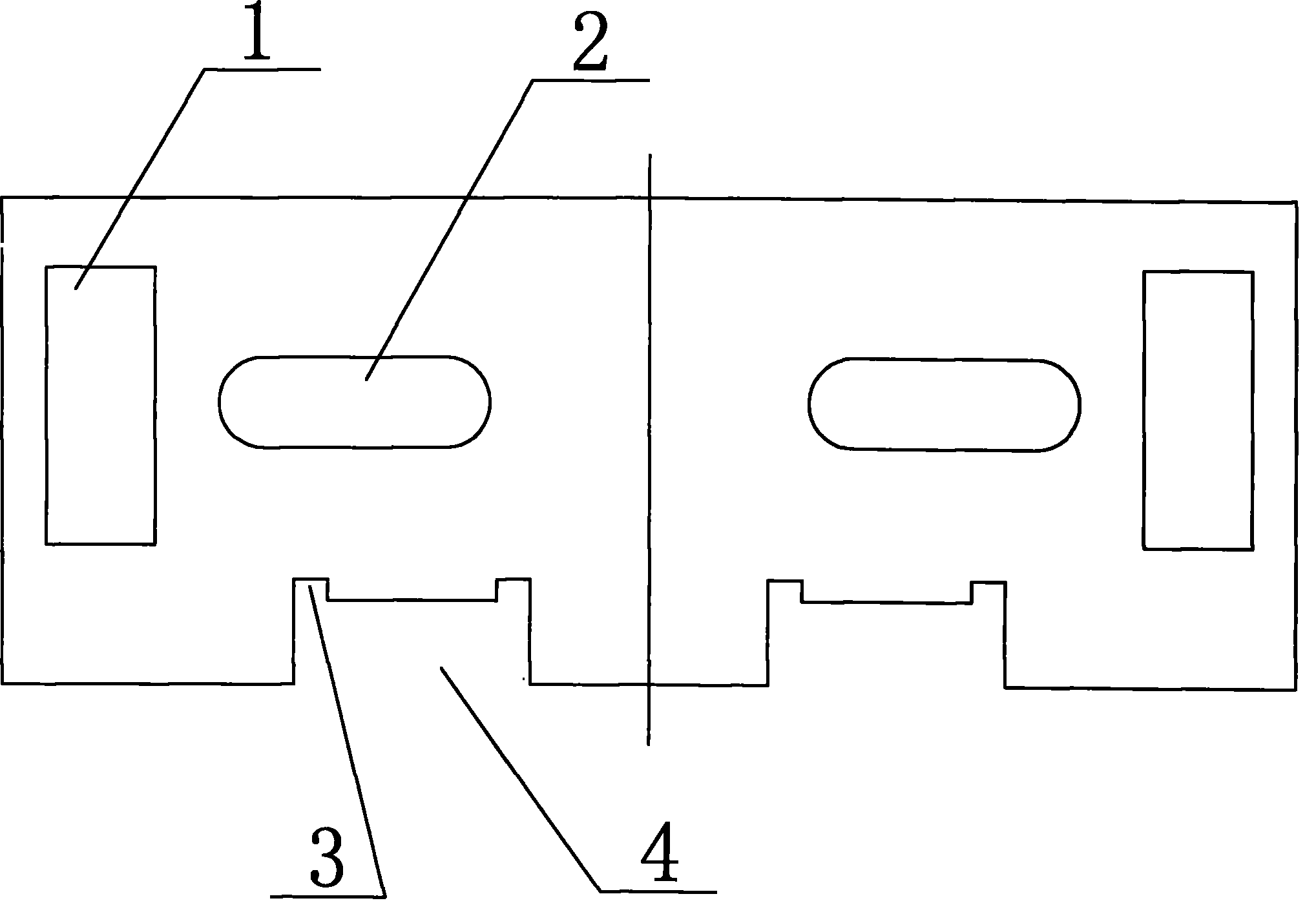
[0014] like figure 2 As shown, the traveler steel wire cutting knife of the present invention is composed of a knife holder and an alloy cutter head. Two waist circular positioning holes 2 and two square connections for connecting with the hook on the central axis of the hydraulic cylinder are provided on the knife holder. Holes 1 and two gaps 4 inlaid with alloy cutter heads, each bottom end of the gap 4 is respectively provided with two insert grooves 3, the positioning hole 2, the connecting hole 1 and the gap 4 are defined by the long side of the upper surface of the tool holder. The center line of the blade is arranged symmetrically on the left and right, and the alloy cutter head matched with the blade holder has double-sided blades.

[0015] The distance between the two insert grooves 3 in the above-mentioned notch 4 is 25-40 mm, preferably 30 mm.


PUM


Abstract

The invention discloses a steel wire cutter of a steel wire ring, comprising a cutter rest and an alloy cutter head, wherein the cutter rest is provided with two positioning holes, two connecting holes and two notches, wherein the two connecting holes are used for being connected with hooks on a central shaft of a hydraulic cylinder, the alloy cutter head is embedded in the two notches, the bottom end of each notch is provided with two cutter embedding grooves, the positioning holes, the connecting holes and the notches are symmetrically arranged left and right according to the center line of the longer side on the upper surface of the cutter rest, and the alloy cutter head matched with the cutter rest is provided with a double-sided blade. Compared with the prior art, the cutter rest of the cutter is designed into a left and right symmetrical structure, the alloy cutter head with the double-sided blade is selected to be matched with the cutter rest, when one side of the cutter is unavailable due to gaps on blade, the other side can be replaced for continuous use, and moreover, the operation can be achieved just by independently replacing the alloy cutter head, without dismantling the whole cutter from the hydraulic cylinder, therefore, the invention has the advantages of shortening production period, reducing cost and workload and improving equipment utilization ratio.

Description

technical field [0001] The invention relates to a bead ring steel wire cutter for making tire bead rings. Background technique [0002] The wire cutter on the traveler winding machine consists of a knife holder and an alloy cutter head. The structure of the tool rest of the existing cutting knife is: there are 2 positioning holes on the knife rest, 1 connecting hole for connecting with the hook on the central shaft of the hydraulic cylinder, and 2 notches inlaid with alloy cutter heads. Each end is equipped with an insert groove, which is used to inlay the alloy bit, such as figure 1 shown. The existing cutting knife of this structure is an asymmetrical single-sided cutting knife, that is, it can only be cut with one side of the cutting knife. (Including knife holder and alloy head) Remove and re-insert a new alloy head. This operation is not only time-consuming and labor-intensive, but also increases costs, and the utilization rate of equipment is also low. Contents o...

Claims


Application Information

Patent Timeline
IPC IPC(8): B29D30/48B21F37/00
Inventor 张勋
Owner HAOHUA SOUTH CHINAGUILIN RUBBER
Why Eureka
Try Eureka