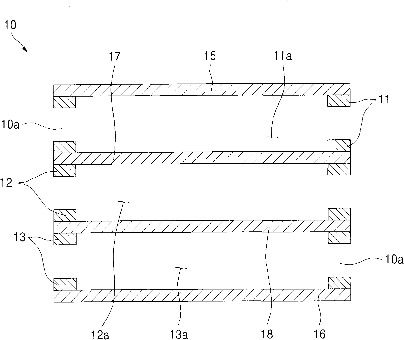
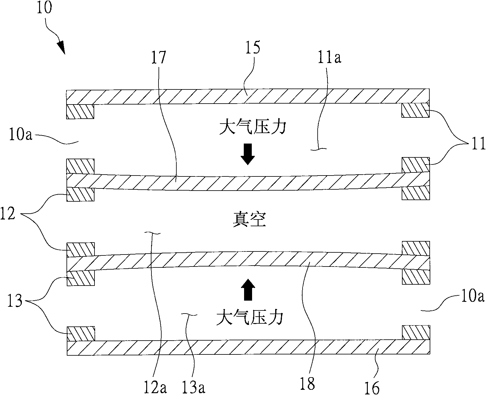
Charging chamber for chemical vapor phase deposition device

A chemical vapor deposition, loading chamber technology, applied in the field of loading chambers, can solve problems such as influence and poor process, and achieve the effects of reduced manufacturing, improved productivity, and reduced bending

Inactive Publication Date: 2011-02-09
SFA CO LTD
View PDF3 Cites 0 Cited by
  • Summary
  • Abstract
  • Description
  • Claims
  • Application Information

AI Technical Summary

Problems solved by technology

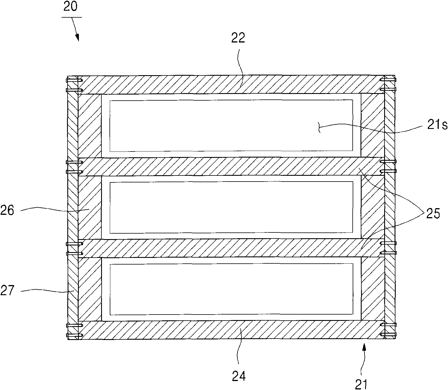
As a result, the particles can be produced from the joint between the upper wall 22, the lower wall 24, the partition wall 25 and the side wall 26 forming the cavity 21, or from the joint between the cavity 21 and the bracket joint 27. Produced by the Ministry, so it will have a bad influence on the process

Method used


Image

  • Charging chamber for chemical vapor phase deposition device
  • Charging chamber for chemical vapor phase deposition device
  • Charging chamber for chemical vapor phase deposition device

Examples


Embodiment Construction

[0048] The present invention has been claimed at the Korea Intellectual Property Office by filing Korean Patent Application No. 10-2007-0119236 on November 21, 2007, Korean Patent Application No. 10-2007-0131150 on December 14, 2007, and The advantages of Korean Patent Application No. 10-2008-0027927 filed on March 26, 2008 are disclosed in full as follows.

[0049] The accompanying drawings are used to illustrate the embodiments of the present invention, and are cited to gain a sufficient understanding of the present invention and its advantages. Hereinafter, embodiments of the present invention are explained and described in detail with reference to the accompanying drawings. And the same reference element number refers to the same element.

[0050] The following description is for reference. A substrate mentioned below may refer to a flat panel display, including a liquid crystal display (LCD) substrate, a plasma display panel (PDP) substrate and an organic light emitting ...


PUM


Abstract

The invention relates to a charging chamber for a chemical vapor phase deposition device, which includes a cavity; a plurality of single chambers containing a substrate therein; a plurality of cavity slots enabling the substrate to input and output therethrough and formed at side surfaces relative to the single chambers; and at least one reinforcing plate which is at least connected to side surfaces of the cavity provided with the cavity slots, wherein, the strength if the reinforced cavity can avoid from generating a bending stress caused by the differential pressure between the single chambers.

Description

[0001] This application is a divisional application. The invention name of the original application is "loading chamber for chemical vapor deposition equipment", the application number of the original application is: 200810180988.9, and the filing date of the original application is November 20, 2008. technical field [0002] The invention relates to a loading chamber, in particular to a loading chamber for chemical vapor deposition equipment which can minimize structural deformation by strengthening the strength of the structure to avoid bending stress caused by pressure difference. Background technique [0003] Flat panel displays have been widely used in television products, computer screens, or personal portable terminals. The flat panel display may include a liquid crystal display (liquid crystal display, LCD), a plasma display panel (plasma display panel), and an organic light emitting diode (organic light emitting diode). Among these flat-panel displays, liquid crysta...

Claims


Application Information

Patent Timeline
IPC IPC(8): C23C16/44
Inventor 李相琝朴相泰
Owner SFA CO LTD
Why Eureka
Try Eureka