Device for controlling ignition and quenching by trigger circuit

A technology of trigger circuit and trigger terminal, applied in ignition safety device, engine ignition, spark ignition controller, etc., can solve problems such as poor contact, transformer damage, battery loss and so on

Inactive Publication Date: 2011-02-09
南通哥班玻璃纤维制品有限公司
View PDF8 Cites 0 Cited by
  • Summary
  • Abstract
  • Description
  • Claims
  • Application Information

AI Technical Summary

Problems solved by technology

[0002] The flameout control of the motorcycle DC igniter adopts a high-voltage short-circuit structure to the ground, such as the first capacitor in the drawing of the manual, and a flameout line is connected at this position, and the capacitor cannot store electric energy through the short circuit of this line, so as to achieve control The role of motorcycle high-voltage ignition output, this structure is simple, but there are obvious shortcomings: 1. Although the capacitor cannot store electric energy, the first line of the transformer is connected to the positive pole of the battery for a long time, so that when the igniter does not work, the battery is always Discharge the transformer, resulting in battery loss and damage to the transformer
2. Because the voltage of the first capacitor is about 400V, using short circuit to control the flameout will cause the contact point of the flameout switch and the main switch to be coked due to the action of the arc, resulting in poor contact and difficult flameout failure

Method used


Image

  • Device for controlling ignition and quenching by trigger circuit
  • Device for controlling ignition and quenching by trigger circuit

Examples


Embodiment Construction

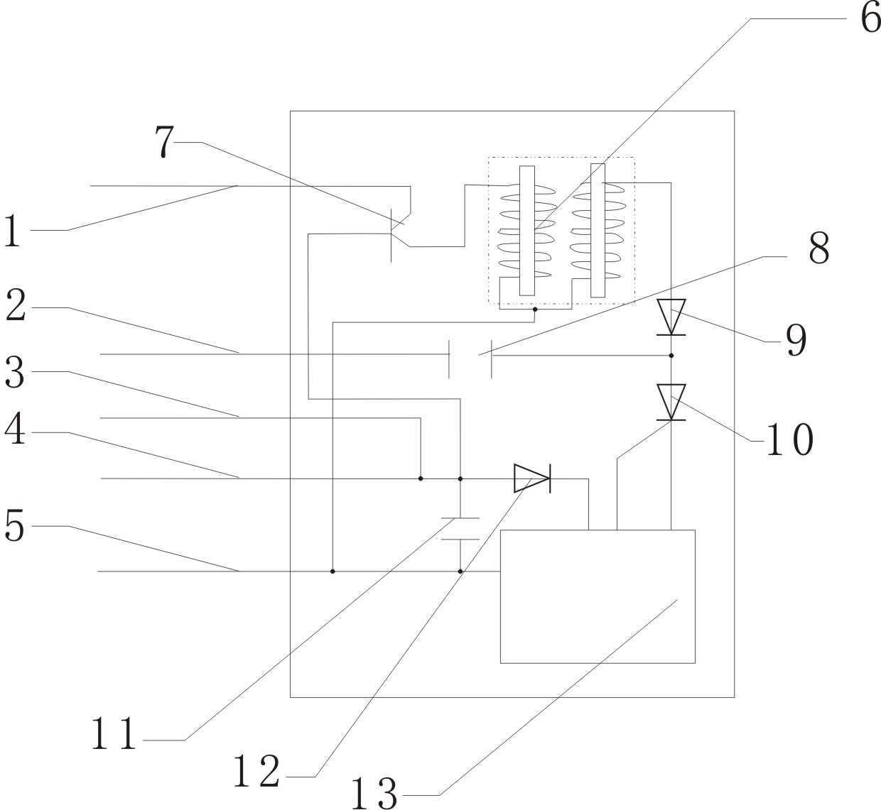
[0008] The accompanying drawing is a structure diagram of a trigger circuit control ignition and extinguishing device of the present invention in a DC igniter, and its structure is composed of a second capacitor 11 and a triode 7 . In the accompanying drawings, one end of the second capacitor 11 is connected to the fifth line 5, the other end is connected to the fourth line 4, and simultaneously connected to the trigger terminal of the triode 7, and the collector of the triode 7 is connected to the first line 1. The electrodes are connected to the primary of the transformer 6 . In this combination, the second capacitor 11 is used to balance the trigger terminal voltage of the triode 7 to ensure reliable conduction of the triode 7 . Except that the second capacitor 11 and the triode 7 are added protection control circuits in the accompanying drawings, the rest are standard configurations of the original igniter itself.

[0009] The fifth line 5 is the negative pole of th...


PUM


Abstract

The invention relates to a device for controlling ignition and quenching by a trigger circuit, which comprises a second capacitor and a triode. The device is characterized in that one end of the second capacitor is connected with a fifth line, the other end thereof is connected with a fourth line and synchronously connected to a triggering end of the triode in parallel, a collector electrode of the triode is connected with a first line, and a discharge electrode is connected with a primary level of a transformer. The device for controlling ignition and quenching by the trigger circuit has the functions that a switch is controlled by utilizing a low voltage and meanwhile a positive electrode power supply can be switched off.

Description

technical field [0001] The invention relates to a flameout control device of a motorcycle igniter, in particular to a trigger circuit controlled ignition and flameout device. Background technique [0002] The flameout control of the motorcycle DC igniter adopts a high-voltage short-circuit structure to the ground, such as the first capacitor in the drawing of the manual, and a flameout line is connected at this position, and the capacitor cannot store electric energy through the short circuit of this line, so as to achieve control The role of motorcycle high-voltage ignition output, this structure is simple, but there are obvious shortcomings: 1. Although the capacitor cannot store electric energy, the first line of the transformer is connected to the positive pole of the battery for a long time, so that when the igniter does not work, the battery is always The discharge of the transformer will cause the battery to lose power and the transformer to be damaged. 2. Because th...

Claims


Application Information

Patent Timeline
Patent Type & Authority Applications(China)
IPC IPC(8): F02P11/00
Inventor 庄景阳
Owner 南通哥班玻璃纤维制品有限公司
Why Eureka
Try Eureka