LED (Light-Emitting Diode) bypass control circuit and control method thereof

A technology for controlling circuits and circuits, which is applied to the layout of electric lamp circuits, electric light sources, and electrical components. It can solve problems such as current surges, voltage regulator tubes that cannot automatically recover, and inconvenient restarts. It achieves power consumption reduction and circuit structure. simple effect

Active Publication Date: 2011-02-09
CHENGDU MONOLITHIC POWER SYST
View PDF3 Cites 15 Cited by
  • Summary
  • Abstract
  • Description
  • Claims
  • Application Information

AI Technical Summary

Problems solved by technology

Secondly, when the Zener diode ZD is mistriggered, for example, when the power supply voltage is unstable and produces a "spike" or the current surge at the moment the LED is turned on, one or more Zener diodes ZD in the light string will conduct in reverse. Bypass

Method used


Image

  • LED (Light-Emitting Diode) bypass control circuit and control method thereof
  • LED (Light-Emitting Diode) bypass control circuit and control method thereof
  • LED (Light-Emitting Diode) bypass control circuit and control method thereof

Examples


Embodiment Construction

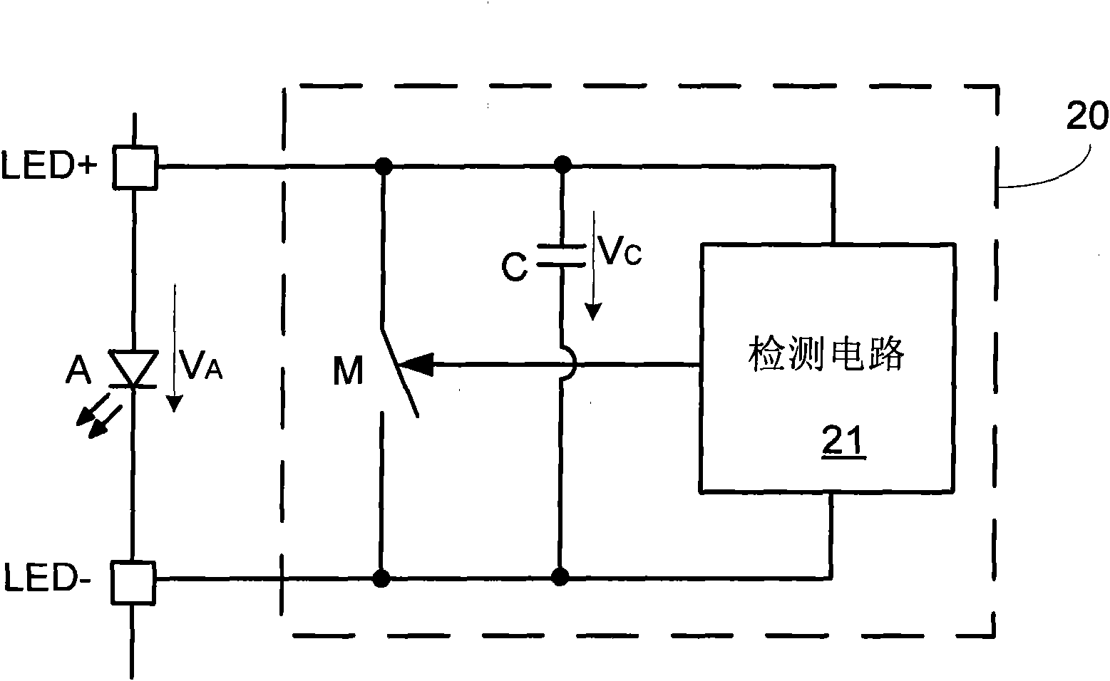
[0018] Figure 2a One embodiment of a control circuit 20 for bypassing LEDs of the present invention is shown. The control circuit 20 is coupled in parallel to both ends of the target circuit LED A, and performs bypass control on the LED A according to the state of the target circuit. For example, the control circuit 20 may turn on the bypass circuit to bypass the LED A when it detects that the forward voltage across the LED A exceeds a predetermined voltage according to the detected voltage across the LED A. Each component of the control circuit 20 will be specifically described below.

[0019] The control circuit 20 includes a detection circuit 21 , a bypass circuit and a capacitor C. Wherein the bypass circuit is a bypass switch M. The bypass switch M and the LED A are connected in parallel, and the control terminal of the bypass switch M is controlled by the output signal of the detection circuit 21 and is selectively turned on to bypass the LED A. The detection circui...


PUM


Abstract

The invention discloses an LED bypass control circuit which comprises a detecting circuit, a switch and a capacitor. The detecting circuit is coupled to both ends of a target LED and used for detecting the state of the LED; and a bypass switch is connected in parallel with the LED and selectively conducted according to an output signal of the detecting circuit to bypass the LED. In the invention,the conducting state of the switch is maintained for a certain time through the capacitor, the LED bypass control circuit has lower power consumption compared with a traditional voltage-stabilizing tube bypass element, and meanwhile, an LED system can automatically restore the normal working state when in false triggering.

Description

technical field [0001] The present invention relates to LEDs, in particular to LED bypass control circuits and control methods thereof. Background technique [0002] Light-emitting diode (LED) backlight applications in the display field began to dominate. For example, in the field of LCD TVs, LEDs are gradually replacing traditional CCFL backlight sources. In LCD TV backlight applications, LEDs provide backlight in the form of an array of multiple light strings. Such as figure 1 As shown, each string composed of multiple LED lights in series is driven by a DC voltage of up to 200V. This series LED light string has the advantage that the current of each LED light is the same, therefore, the brightness is stable and the driving efficiency is high. But the LED light string also has a big disadvantage, that is, when one LED in the light string is open circuit, the whole light string will go out. [0003] To prevent this problem, a bypass circuit is usually used in parallel ...

Claims


Application Information

Patent Timeline
IPC IPC(8): H05B37/02H05B44/00
CPCH05B33/0887H05B45/54
Inventor 席小玉张正伟
Owner CHENGDU MONOLITHIC POWER SYST
Why Eureka
Try Eureka