Applying a control unit to an asynchronous machine which is operated without a rotary encoder

A technology for asynchronous motors and control equipment, applied in the direction of controlling generators, controlling electromechanical brakes, controlling electromechanical transmissions, etc., can solve problems such as time requirements, and achieve the effect of shortening the synchronization time

Active Publication Date: 2011-02-09
LENZE DRIVES
View PDF7 Cites 6 Cited by
  • Summary
  • Abstract
  • Description
  • Claims
  • Application Information

AI Technical Summary

Problems solved by technology

Disadvantages of the search method described are the time requirement for the identification of the mechanical rotational speed and the applied torque due to magnetization

Method used


Image

  • Applying a control unit to an asynchronous machine which is operated without a rotary encoder
  • Applying a control unit to an asynchronous machine which is operated without a rotary encoder
  • Applying a control unit to an asynchronous machine which is operated without a rotary encoder

Examples


Embodiment Construction

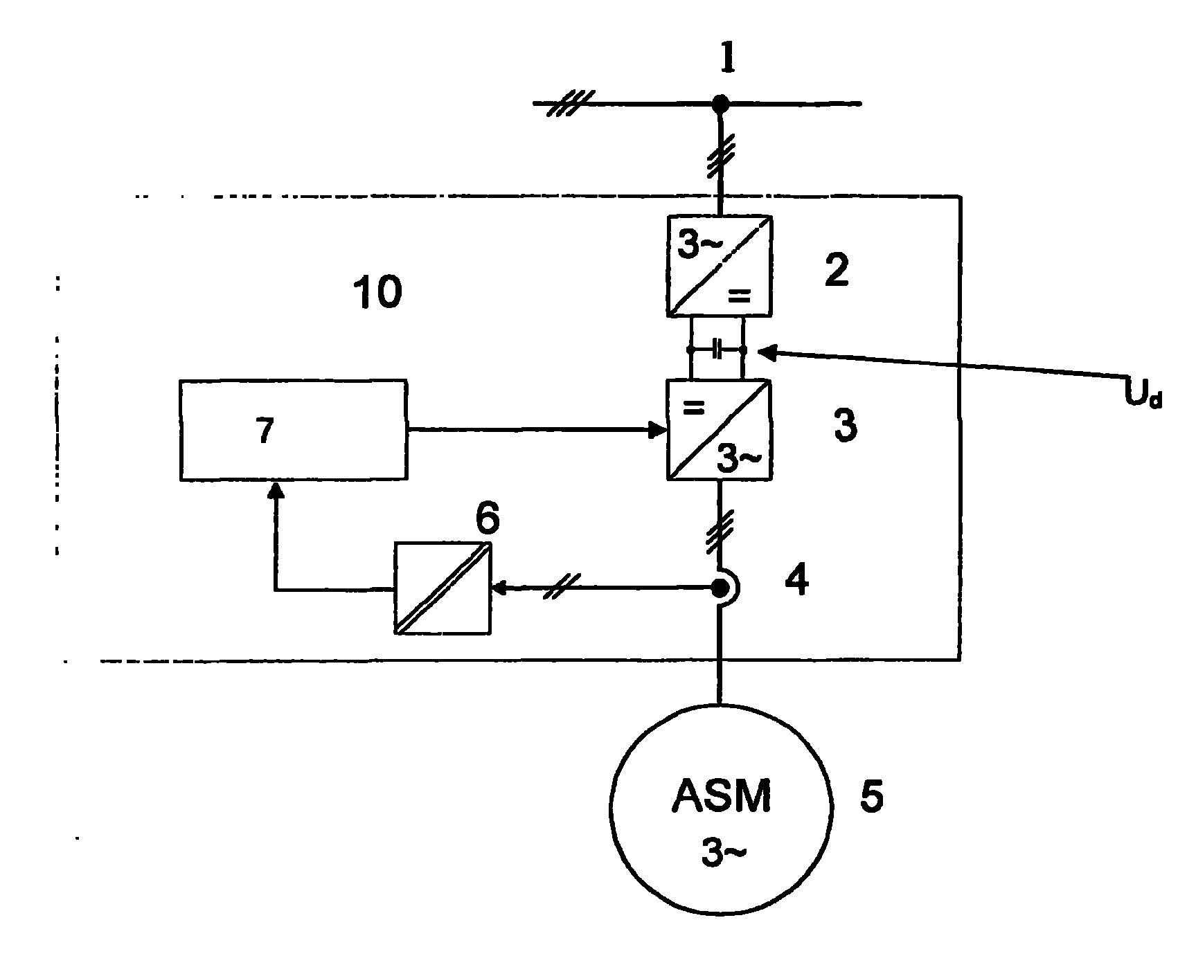
[0048] image 3 A device for implementing an example of the method according to the invention is shown in a principled manner.

[0049] Among them, the grid voltage 1 is rectified by the rectifier 2 into a DC voltage U d , the DC voltage U d It is supplied to the inverter or frequency converter 3 as an intermediate circuit voltage. The inverter or frequency converter 3 is a power control device for an asynchronous motor. An asynchronous motor 5 (DAM or ASM) is connected to the output of the inverter. The control device 10 for the DAM 5 contains a regulating device 7 which is fed by the current measuring device 4 .

[0050] The power semiconductor switches of the frequency converter or inverter 3 are controlled by a control circuit which is controlled by a regulator. At least two of the three motor phase currents (encoder 4 and coupling device 6 ) are detected and supplied to a control system 7 . Within the regulation system, the stator current vector is determined from t...


PUM


Abstract

The problem of the invention is to achieve a connection or application of a converter to a rotating asynchronous machine, which is operated without an encoder, without a high current and without a torque surge. The mechanical system and the controlling system are not to be overloaded. The method is also to be capable of functioning independently of the residual magnetism. A method is proposed as a control unit, which employs an inverter or converter, in order to power the asynchronous machine (5), which rotates at a mechanical speed. The asynchronous machine is regulated by the control unit. A stator current vector (i s) is ascertained from measured currents of the stator windings of the asynchronous machine (5) and a rotating stator voltage vector (u s). A calculation of a stator flux change vector is performed from the stator current vector (i s), the stator voltage vector (u s), and a stator resistance (RS) according to a motor model (100). An angle difference (gamma) between the stator current vector (i S) and the stator change vector is calculated. This angle difference (gamma) is regulated to a target value of 90 DEG or -90 DEG , wherein an output signal of said controller corresponds to a rotating field frequency (omega) of the voltage vector of said stator which is to be applied. A regulation of an amplitude of the stator voltage vector is performed via a current controller (51), to which the difference of a current target value and a variable which corresponds to the amplitude of the stator current is provided at the input as the control difference (51a).

Description

technical field [0001] The method according to the invention is used to connect or connect an inverter or a frequency converter (as a control unit) to a stationary or rotating asynchronous machine. Generally speaking, the control device is not synchronized with the machine. The method is used for asynchronous motors in which the rotational speed is not fed back to an inverter or frequency converter (encoderless operation), so that there is no current mechanical rotational speed for the asynchronous motor (as actual rotational speed ) for any information. Background technique [0002] The control unit must be connected to and synchronized with a rotating or stationary asynchronous motor (ASM or DSM). [0003] In the case of an asynchronous machine operated without an encoder, the identification process of the mechanical rotational speed or of the synchronous rotating field frequency is referred to in the literature as "catch operation", see eg Witt & Sohn, Regulation of fre...

Claims


Application Information

Patent Timeline
Patent Type & Authority Applications(China)
IPC IPC(8): H02P21/12H02P21/00
CPCH02P21/0039H02P21/0032H02P21/12H02P21/0003H02P1/029H02P21/34H02P21/24
Inventor H·施第西韦
Owner LENZE DRIVES
Why Eureka
Try Eureka