
Floating-ship trough-type blade-load-adjustable water turbine water power station

A hydraulic turbine and power station technology, applied in hydroelectric power stations, hydroelectric power generation, renewable energy power generation, etc., can solve problems such as failure to achieve the purpose of power generation, failure to adjust the load of the turbine, failure to meet the power frequency of the power grid, etc.

Inactive Publication Date: 2012-05-30
张志国
View PDF3 Cites 0 Cited by
  • Summary
  • Abstract
  • Description
  • Claims
  • Application Information

AI Technical Summary

Problems solved by technology

For example: the prior art design does not have the function of speed increase and speed regulation of the turbine, and cannot meet the power frequency of the power grid; the prior art design has no clutch device, and does not have the ability to adjust the phase angle of power generation; the prior art design has no power control device, and cannot realize the adjustment of the turbine load; some technical designs cannot achieve its power generation purpose, its technical design is incomplete, and its overall functional structure is incomplete

Method used


Image

  • Floating-ship trough-type blade-load-adjustable water turbine water power station
  • Floating-ship trough-type blade-load-adjustable water turbine water power station
  • Floating-ship trough-type blade-load-adjustable water turbine water power station

Examples


Embodiment Construction

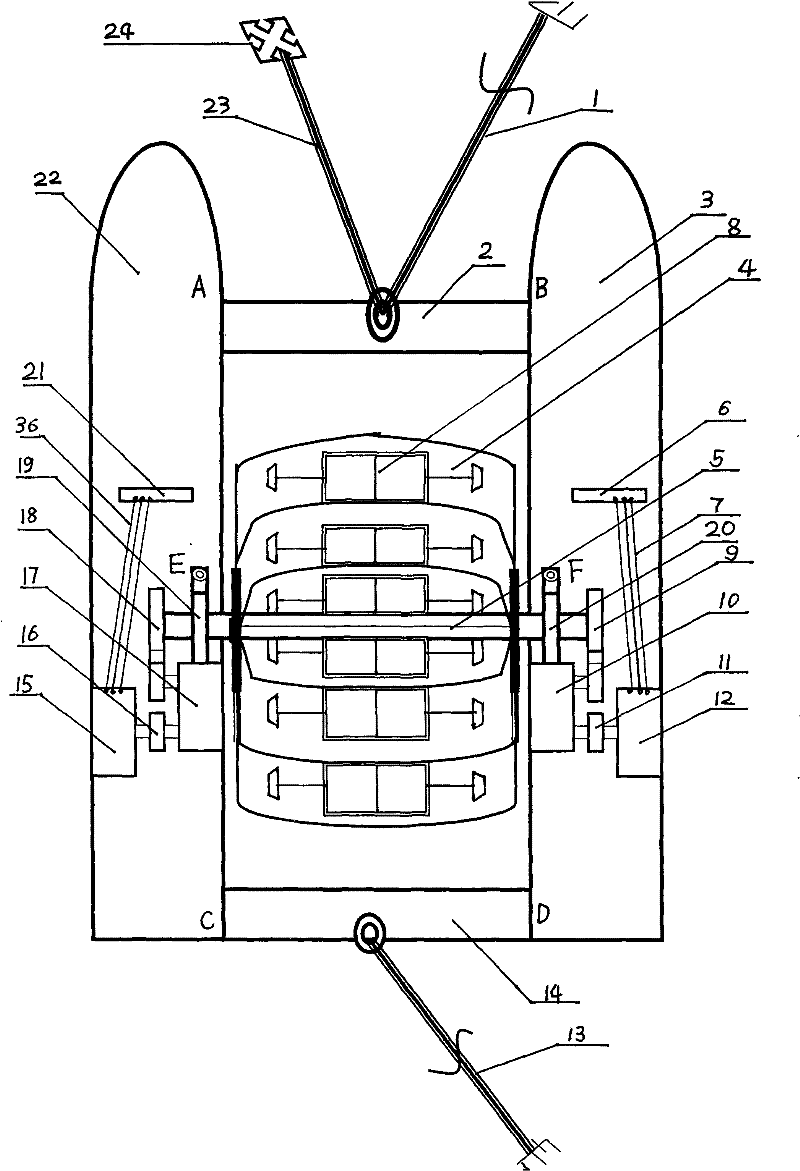
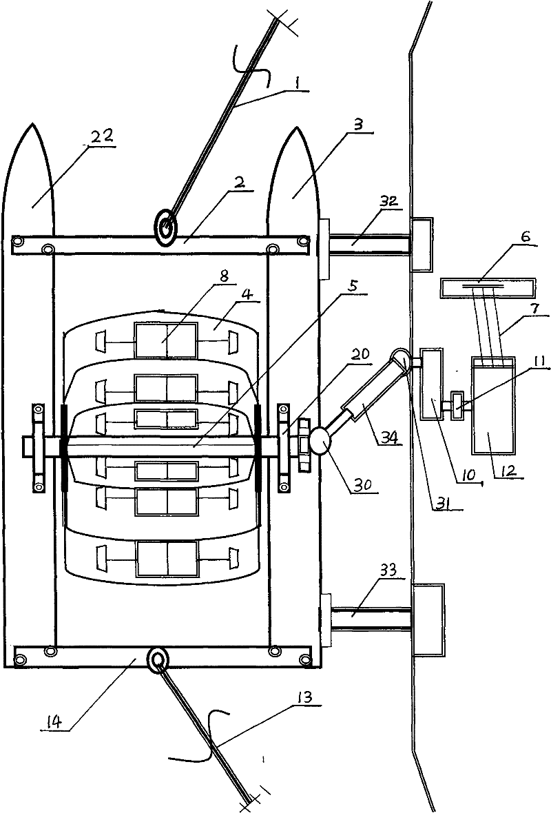
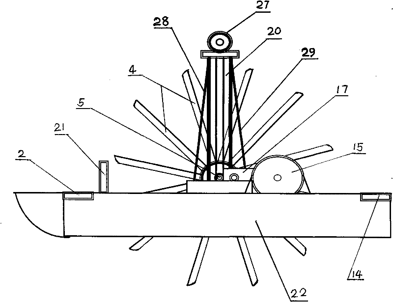
[0018] as attached figure 1 As shown: in the natural river current, the floating boat type hydraulic turbine power station is composed as follows: it includes the right floating boat 3 and the left floating boat 22, the buoyancy of which meets the weight bearing requirements of the hydropower station, and the horizontal distance between them can place the turbines 5. Use the front I-beam connecting beam 2 to connect the two floating boats at A of the right floating boat 3 and B of the left floating boat 22, and fix and weld them firmly. The D place of the floating boat 22 uses the rear I-beam connecting beam 14 to connect the two floating boats together, and the fixing welding is firm, so that the right floating boat 3 and the left floating boat 22 are combined into a rigid integral structure. Through the double pulling of the fixed steel wire pull rope 1 on the front river bank, the fixed steel wire pull rope 13 on the back river bank and the steel wire pull rope 23 of the bo...


PUM


Abstract

The invention relates to a floating-ship trough-type blade-load-adjustable water turbine water power station, belonging to a power generation technology by utilizing natural river water flow. The invention collects water flow kinetic energy by using a floating-ship trough-type blade-load-adjustable water turbine, and converts the water flow kinetic energy into mechanical energy, thereby driving agenerator to generate power. A water turbine is carried by two parallel floating ships; the lateral distance between the two floating ships can accommodate the trough-type blade-load-adjustable waterturbine; an I-shaped steel beam connects the two ship hulls together to constitute a rigid overall structure; and under the dual pull actions of a steel wire pull rope fixed to the riverside and an anchor steel wire pull rope of the river bottom, the water turbine can float on a natural river safely and stably so as to collect the impact kinetic energy of the water flow. The generator, a control system and the shipborne water turbine are floated on the ships in the river to generate power; or the generator and the control system are separated from the shipborne water turbine and fixed on the riverside, and a universal joint telescopic transmission shaft is used for transmitting the power torque of the water turbine on the floating ships to the shaft of the generator, thereby driving the generator to generate power.

Description

technical field [0001] The utility model relates to a floating ship type power station, in particular to a floating ship type water turbine power station utilizing the flow energy of natural river water. Background technique [0002] The existing technology of utilizing natural river currents to impact floating ship type water turbines to generate electricity has flaws and deficiencies in technology because of its imperfect overall functional structure design and unreasonable mechanism settings. For example: the prior art design does not have the function of speed increase and speed regulation of the turbine, and cannot meet the power frequency of the power grid; the prior art design has no clutch device, and does not have the ability to adjust the phase angle of power generation; the prior art design has no power control device, and cannot realize the adjustment of the turbine load; some technical designs cannot achieve its power generation purpose, its technical design is ...

Claims


Application Information

Patent Timeline
Patent Type & Authority Patents(China)
IPC IPC(8): F03B13/00F03B3/14E02B9/00
CPCY02E10/223Y02E10/22Y02E10/20
Inventor 张志国
Owner 张志国
Learn More