Film-breaking device of electric film-breaking shock tube

A technology of shock tube and membrane rupture, which is applied in the field of fluid mechanics research, can solve the problems of poor contact between resistance wire and polyester diaphragm, heavy workload of repeated labor, and impact on shock wave quality, etc., and achieves good rupture symmetry, Good contact, excellent quality results

Inactive Publication Date: 2011-02-16
INST OF FLUID PHYSICS CHINA ACAD OF ENG PHYSICS
View PDF6 Cites 16 Cited by
  • Summary
  • Abstract
  • Description
  • Claims
  • Application Information

AI Technical Summary

Problems solved by technology

[0005] The resistance wire in the existing electro-membrane rupture system is generally made into a "ten" shape by manual winding and then sandwiched in a double-layer polyester diaphragm or attached to a single-layer polyester diaphragm. It is necessary to wind a "ten"-shaped resistance wire, and the workload of repeated labor is relatively large
In addition, because the polyester diaphragm is simply clamped between the high-voltage section and the low-pressure section, the pressure difference between the high-voltage section and the low-pressure section makes the diaphragm protrude toward the low-voltage section to form a bulge, causing the resistance wire to contact the polyester diaphragm. Defective, causing the asymmetry of the ruptured membrane, thus affecting the quality of the generated shock wave

Method used


Image

  • Film-breaking device of electric film-breaking shock tube
  • Film-breaking device of electric film-breaking shock tube
  • Film-breaking device of electric film-breaking shock tube

Examples


Embodiment Construction

[0043] The present invention will be described in detail below in conjunction with the accompanying drawings.

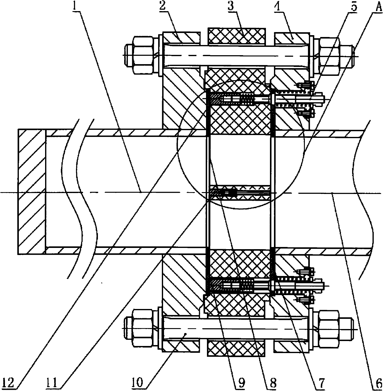
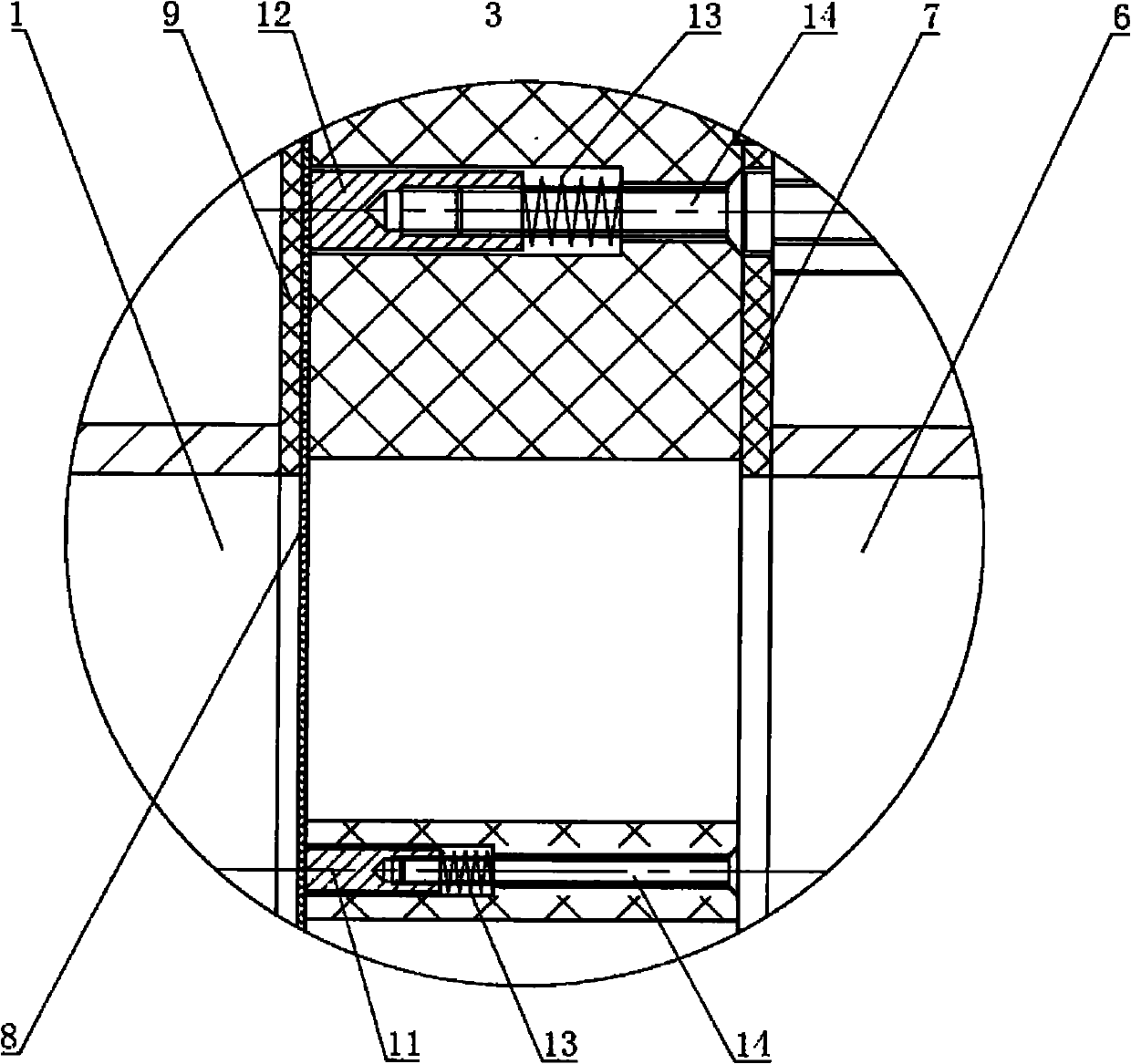
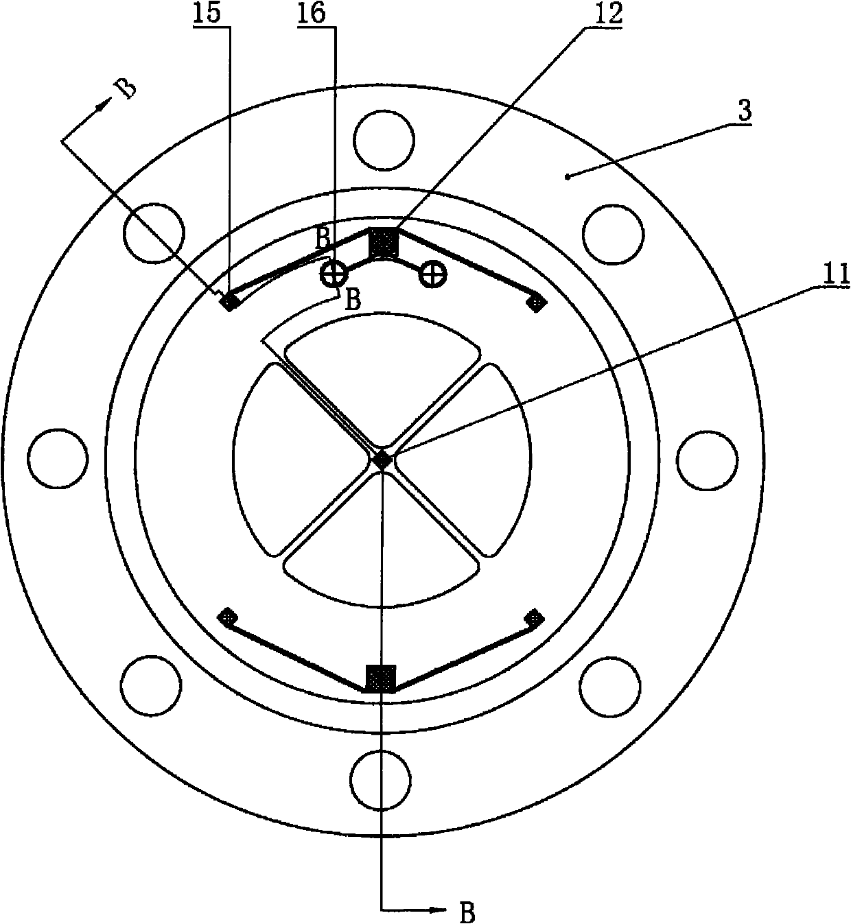
[0044] Such as figure 1 , figure 2 , image 3 , Figure 4 , Figure 5 , Image 6 , Figure 7 , Figure 8 , Figure 9 , Figure 10 , Figure 11 , Figure 12 , Figure 13 , Figure 14 , Figure 15 with Figure 16 As shown, a membrane breaking device for an electro-membrane-breaking shock tube includes a high-pressure section 1 and a low-pressure section 6, and a high-pressure section flange 2 and a low-pressure section flange 4 are respectively provided at the connection ends of the high-pressure section 1 and the low-pressure section 6, and the high-pressure section flange 2 and the flange 4 of the low-pressure section are connected by bolts 10, a membrane breaking device is installed between the high-pressure section 1 and the low-pressure section 6, and a high-pressure section sealing ring 9 is installed between the membrane breaking device and the hi...


PUM


Abstract

The invention relates to a film-breaking device of an electric film-breaking shock tube, which comprises a high-pressure section (1) and a low-pressure section (6) that are connected through a bolt (10), wherein a film-breaking device is arranged between the high-pressure section (1) and the low-pressure section (6). The film-breaking device is characterized by being a circular baffle plate (3), the periphery of which is an annular plate, wherein the center of the circular baffle plate (3) is provided with a center column, ribs are uniformly distributed between the center column and the annular plate, a fan cavity is formed between every two ribs; the annular plate is provided with a power supply binding post (5); a center conducting column (11) is arranged on the center column; a wire fixing post (15) is arranged on the annular plate; a resistor wire (17) is wound between the wire fixing post (15) and the center conducting column (11), each rib forms a bridge frame of the resistor wire (17), the resistor wire (17) is connected through an electric connecting member to form a power supply loop; and an easily-melting film (8) is adhered on the circular baffle plate (3); and the back surface of the easily-melting film (8) is tightly attached to the resistor wire (17) on the bridge frame.

Description

1. Technical field [0001] The invention belongs to the field of fluid mechanics research, and in particular relates to a membrane rupture device of an electric membrane rupture shock wave tube. 2. Background technology [0002] Shock tubes can generate shock waves and use the supersonic pressure waves to simulate the required experimental conditions. They are widely used in many basic researches of physics and chemistry (such as combustion, explosion and unsteady wave motion, etc.). [0003] There are two main types of shock tube membrane rupture: passive and active. Passive membrane rupture is to crush the diaphragm when the pressure difference between the high and low pressure sections reaches a certain value. The membrane rupture pressure can be controlled by the thickness of the diaphragm or the depth of the groove. This method is mainly used in the pressure difference between the high and low pressure sections. In a larger case, the advantage is that the structure is s...

Claims


Application Information

Patent Timeline
Patent Type & Authority Applications(China)
IPC IPC(8): G01M10/00
Inventor 黄文斌谭多望闫石邹立勇刘金宏龚晏青先远中
Owner INST OF FLUID PHYSICS CHINA ACAD OF ENG PHYSICS
Why Eureka
Try Eureka