Device for producing synthesis gas with a gasification reactor and connecting quenching chamber

A gasification reactor and gas technology, which is applied in the field of raw gas equipment, can solve the problems of equipment corrosion aggravation, equipment burden, ash separation, etc., and achieve the effects of improving circulation, strong mixing, and correcting short-term changes

Active Publication Date: 2011-02-23
UHDE GMBH
View PDF9 Cites 2 Cited by
  • Summary
  • Abstract
  • Description
  • Claims
  • Application Information

AI Technical Summary

Problems solved by technology

[0003] In gasifiers of conventional construction type, usually 30% to 60% of the fuel ash is converted into fly ash, which brings disadvantages: deposits can form in the flow path of the raw gas and can cause connections behind it The corrosion of the equipment is aggravated
This l

Method used


Image

  • Device for producing synthesis gas with a gasification reactor and connecting quenching chamber
  • Device for producing synthesis gas with a gasification reactor and connecting quenching chamber
  • Device for producing synthesis gas with a gasification reactor and connecting quenching chamber

Examples


Embodiment Construction

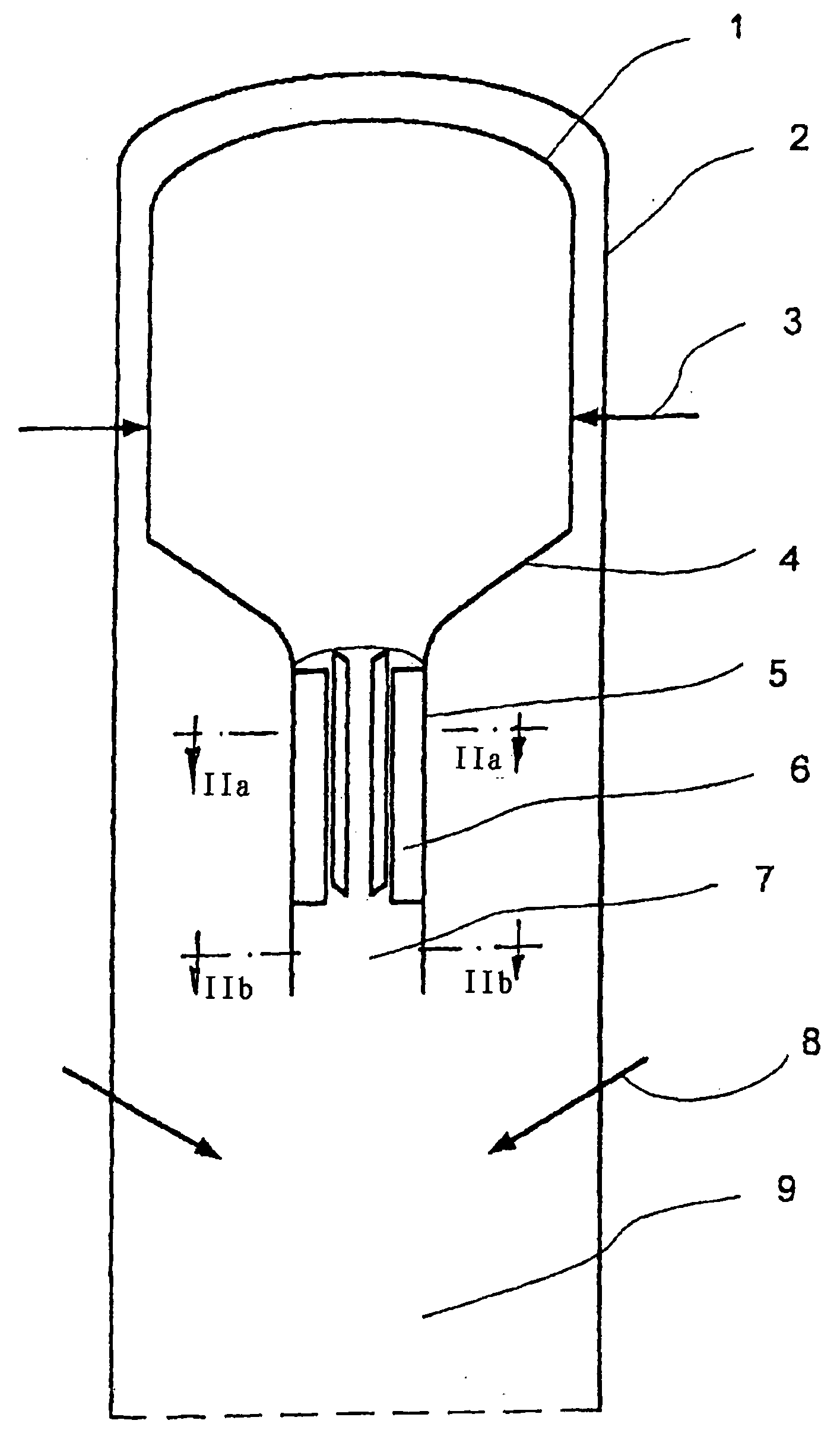
[0047] figure 1A reactor 1 in a high-pressure vessel 2 is schematically shown in a sectional view, wherein only arrows 3 indicate the burners which act on the reactor 1 .

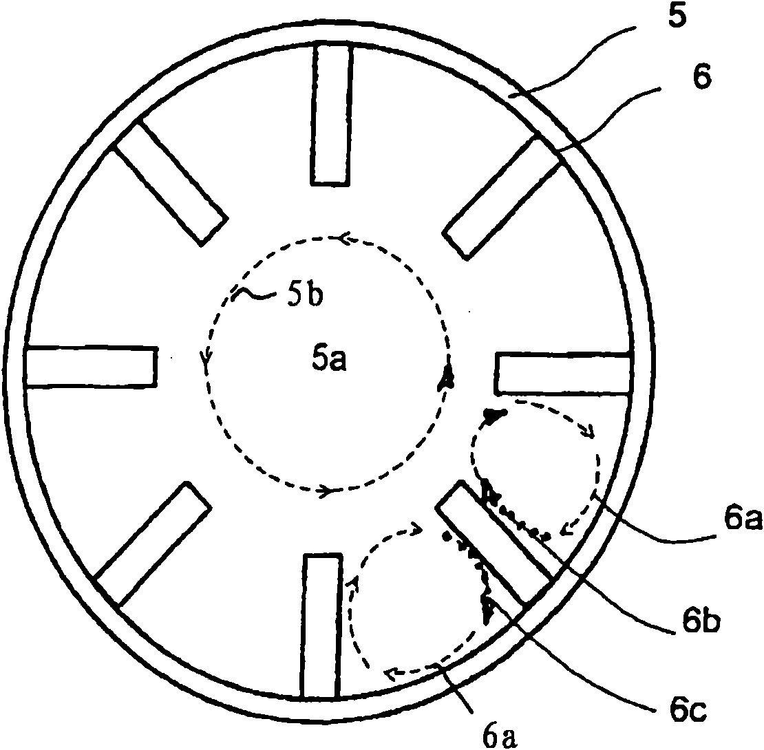
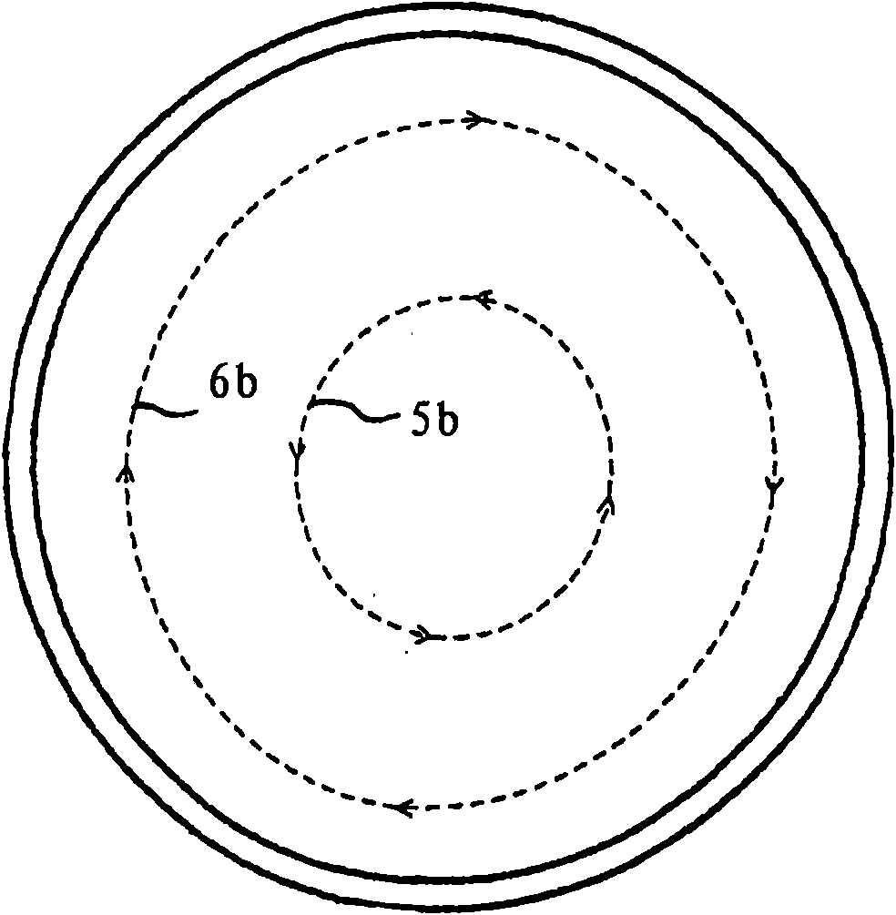
[0048] It can be seen that the funnel-shaped bottom of the gasifier marked at 4 transitions into a narrowing channel 5 provided with elements 6 facing the flow for reducing the turbulence formed by the mixture exiting the reactor .

[0049] In this case, the narrowed channel 5 has a first mixing region 7 downstream of the component 6 in the flow direction, which then opens into a gas-cooling chamber, designated 9, for example a quenching chamber, wherein the quenching medium Delivery is shown with arrow 8 .

[0050] The component facing the air flow can be designed as a duct wall through which the cooling medium flows, as it is described below Figure 5 as detailed. In addition, the pipe walls can be pinned and tamped to facilitate bonding of slag and reduce heat flux.

[0051] exist Figure 2a Shown ...


PUM


Abstract

The invention relates to a device for producing a crude gas containing CO or H2 by gasification of an ash-containing fuel with oxygen-containing gas at temperatures above the fusion temperature of the ash in a gasification reactor and with a connected gas cooling chamber and a tapered connecting channel running from one chamber to the other. The aim of the invention is avoiding known problems and reducing the amount of fly ash and the amount of ungasified fuel, wherein a weak eddy is achieved in the inlet to the subsequent apparatuses in order to avoid deposits there with a very compact device, wherein the risk of solidification of the slag in the outlet is also avoided. The aim is achieved, wherein in the tapered connection channel (5) eddy reducing or eliminating wall surfaces (6) running over only a part of the cross-section of the connection channel are provided.

Description

technical field [0001] The present invention relates to an apparatus for producing raw coal gas containing carbon monoxide and hydrogen by gasifying fuel containing ash with an oxygen-containing gas at a temperature higher than the melting point of ash in a gasification reactor to produce raw coal gas , and has a connected gas cooling chamber, and a narrow transition passage from one chamber to the other. Background technique [0002] Devices of this type are known, for example, from EP 0 616 022 B1 or EP 0 400 740 B1. DE 10 2005 048 488 A also discloses a similar design, and for the prior art, reference should also be made to EP 0 431 266 A1 or DE 10 2006 029 595 A1. [0003] In gasifiers of conventional construction type, usually 30% to 60% of the fuel ash is converted into fly ash, which brings disadvantages: deposits can form in the flow path of the raw gas and can cause connections behind it The corrosion of the equipment is aggravated. Separation and extraction of f...

Claims


Application Information

Patent Timeline
IPC IPC(8): C10J3/50C10J3/52
CPCC10J3/84B01J8/1836B01J2208/00681C10J2300/0956C10J2300/1846C10J3/485C10J2300/1634B01J8/003B01J2208/00761C10J3/526
Inventor J·科沃尔
Owner UHDE GMBH
Why Eureka
Try Eureka