Device state detecting device, device state detecting method, device state detecting server, device state detecting system, liver abnormality detecting device, liver abnormality detecting system, liver abnormality detecting method, and device state d
A technology for equipment status and detection devices, which can be applied to measurement devices, billing equipment, power-consuming devices, etc., can solve problems such as refusing to use devices, and achieve the effects of improving reliability, ensuring safety, and reducing wasteful use of energy.
- Summary
- Abstract
- Description
- Claims
- Application Information
AI Technical Summary
Problems solved by technology
Method used
Image
Examples
Embodiment approach 1
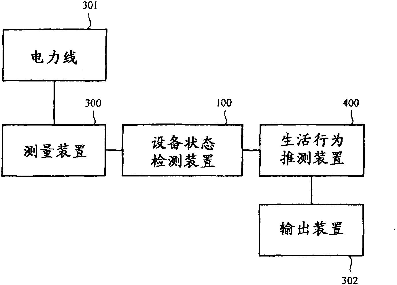
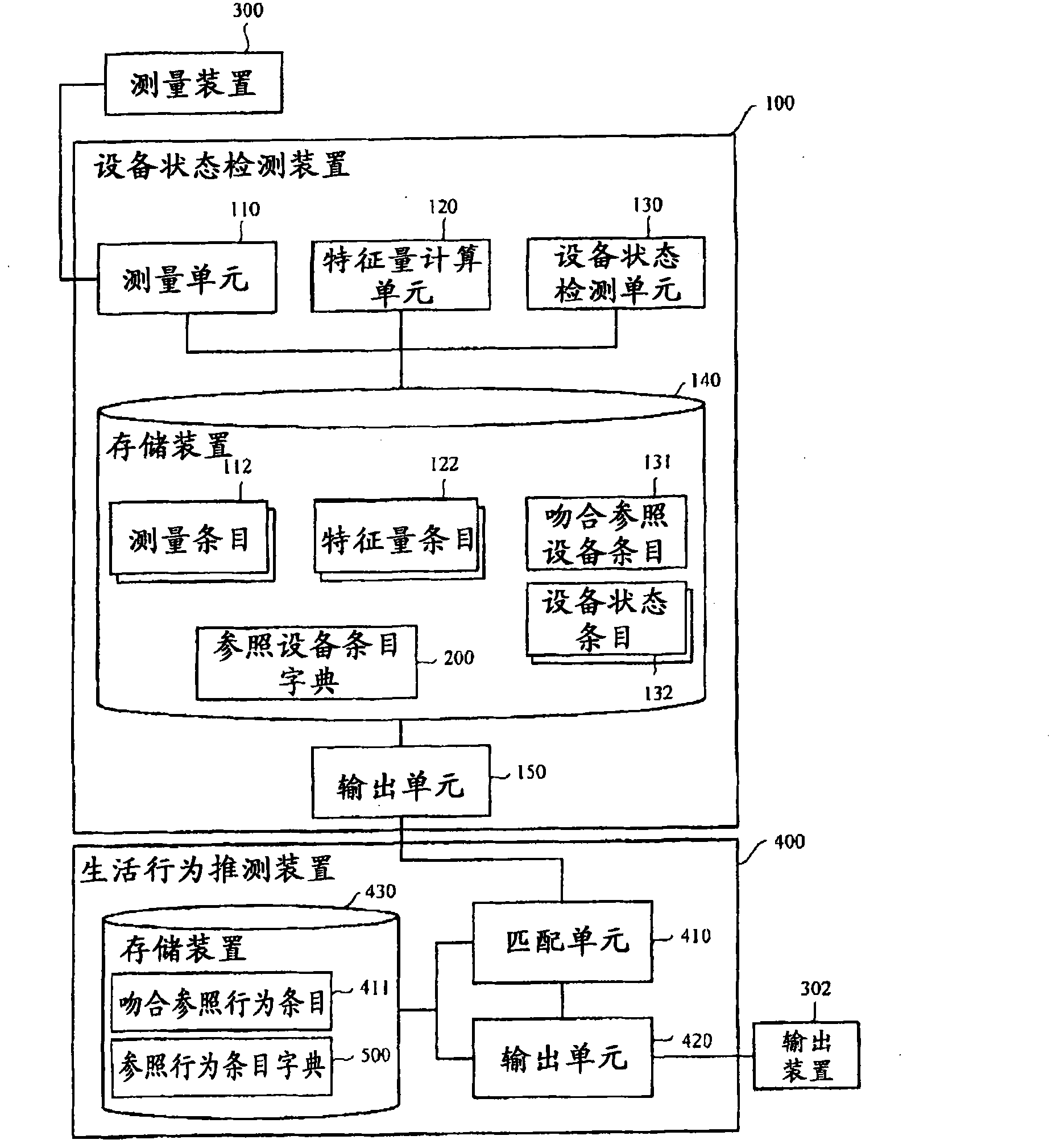
[0077] figure 1 It is a schematic system configuration diagram of a home environment in which the device state detection device 100 according to Embodiment 1 of the present invention is installed. Such as figure 1 As shown, the device state detection device 100 is connected to the measurement device 300 and the life behavior estimation device 400.
[0078] The measuring device 300 is a device for measuring the current of the power supply port of the power line 301, and for example, a current sensor is used. The measuring device 300 is installed in an upstream portion of an extension cord (cord) such as a power supply port of the power line 301 or a station tap or an OA tap.
[0079] The device state detection device 100 detects the device state in the home based on the measurement result of the measurement device 300, and the detected device state is output to the life behavior estimation device 400.
[0080] The life behavior estimation device 400 is a device for estimating the l...
Embodiment approach 2
[0141] In the second embodiment, a calculation method of the feature amount 121a by the feature amount calculation unit 120 will be described. Further elaborate on the Figure 5 Step S603 in. In addition, figure 1 The system structure shown, figure 2 The configurations of the device state detection device 100 and the life behavior estimation device 400 shown are the same as those of the first embodiment, so the description is omitted.
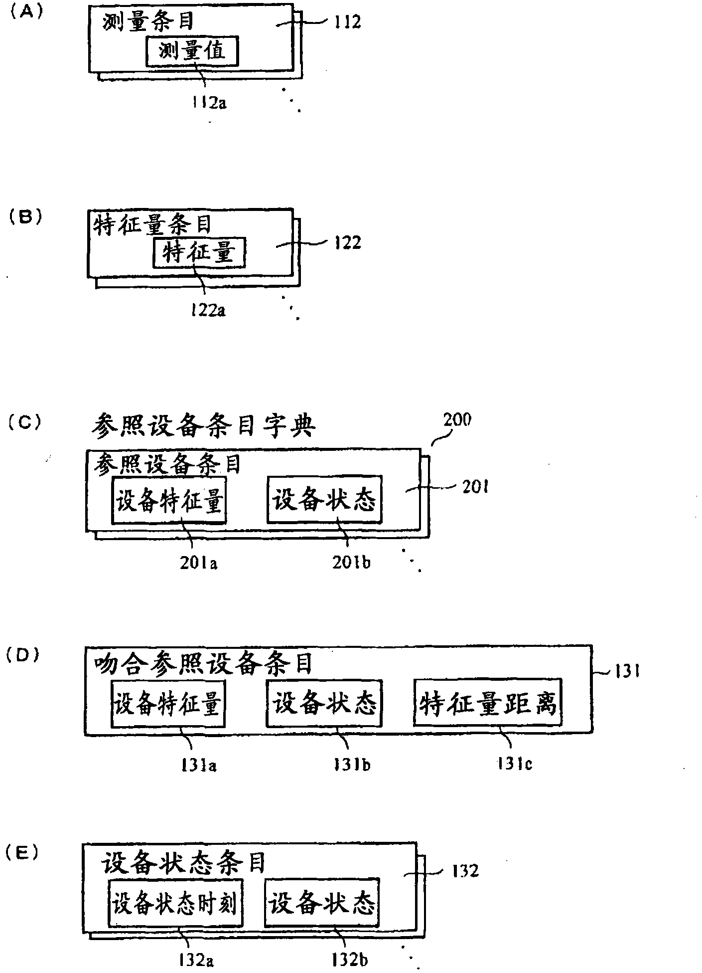
[0142] Figure 7 It is a schematic diagram showing a feature amount calculation method performed by the feature amount calculation unit 120.
[0143] in Figure 7 In (A), the measured value 112a is the measured value of the current measured by the measuring unit 110. When the feature quantity calculation unit 120 receives the measurement value 112a, it calculates the weighted average of the window width 2 for each measurement value 112a-11, 112a-12,...112a-1n constituting the measurement value 112a, and uses this value as the measurement value T...
Embodiment approach 3
[0159] In the third embodiment, a search operation when the device state detection unit 130 searches the reference device entry dictionary 200 will be described. Further elaborate on the Figure 5 Shown in step S605. In addition, figure 1 The system structure shown, figure 2 The configurations of the device state detection device 100 and the life behavior estimation device 400 shown are the same as those of the first embodiment, so the description is omitted.
[0160] In the third embodiment, when the device state detection unit 130 searches the reference device item dictionary 200, it uses an index such as the degree of match of the feature amount to indicate the degree of match between the feature amount item 122 and the reference device item 201. Then, based on the degree of agreement of the feature quantity, it is determined whether or not there is agreement.
[0161] By calculating the difference between the feature amount 122a of the feature amount entry 122 and the value ...
PUM
 Abstract
Description
Claims
Application Information
 - R&D
- Intellectual Property
- Life Sciences
- Materials
- Tech Scout
- Unparalleled Data Quality
- Higher Quality Content
- 60% Fewer Hallucinations
Browse by: Latest US Patents, China's latest patents, Technical Efficacy Thesaurus, Application Domain, Technology Topic, Popular Technical Reports.
© 2025 PatSnap. All rights reserved.Legal|Privacy policy|Modern Slavery Act Transparency Statement|Sitemap|About US| Contact US: help@patsnap.com


