Fuel cell system

A fuel cell system and fuel cell technology, applied in the direction of fuel cells, fuel cell additives, fuel cell heat exchange, etc., can solve problems such as inhalation of air

Inactive Publication Date: 2011-02-23
TOYOTA JIDOSHA KK
View PDF3 Cites 5 Cited by
  • Summary
  • Abstract
  • Description
  • Claims
  • Application Information

AI Technical Summary

Problems solved by technology

[0004] However, in the system described in Patent Document 1, since the inside of the housing is decompressed during the ventilation operation, if there is an inadvertent gap in the housing, air outside the housing may be sucked in from the gap.

Method used


Image

  • Fuel cell system
  • Fuel cell system
  • Fuel cell system

Examples


Embodiment Construction

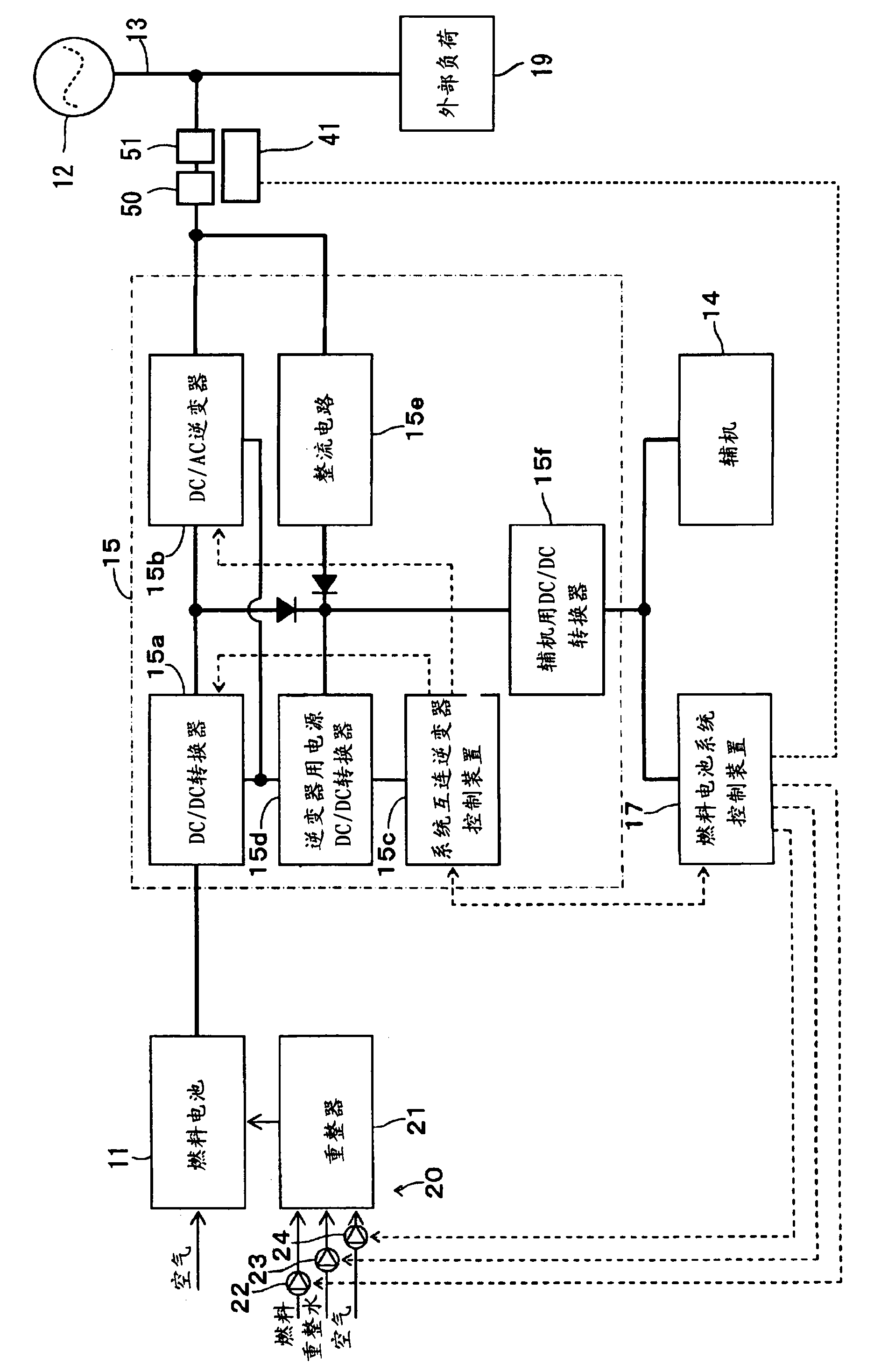
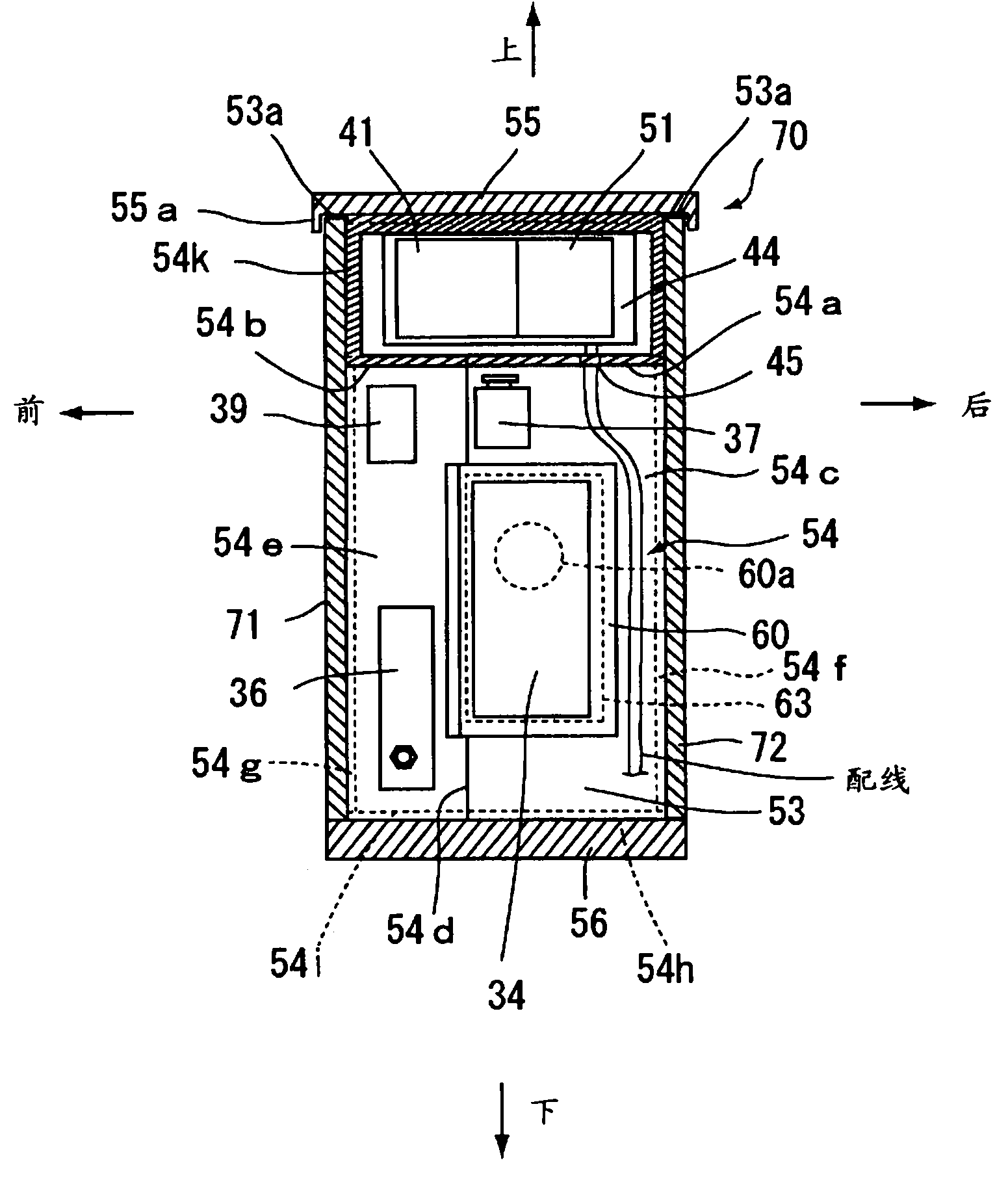
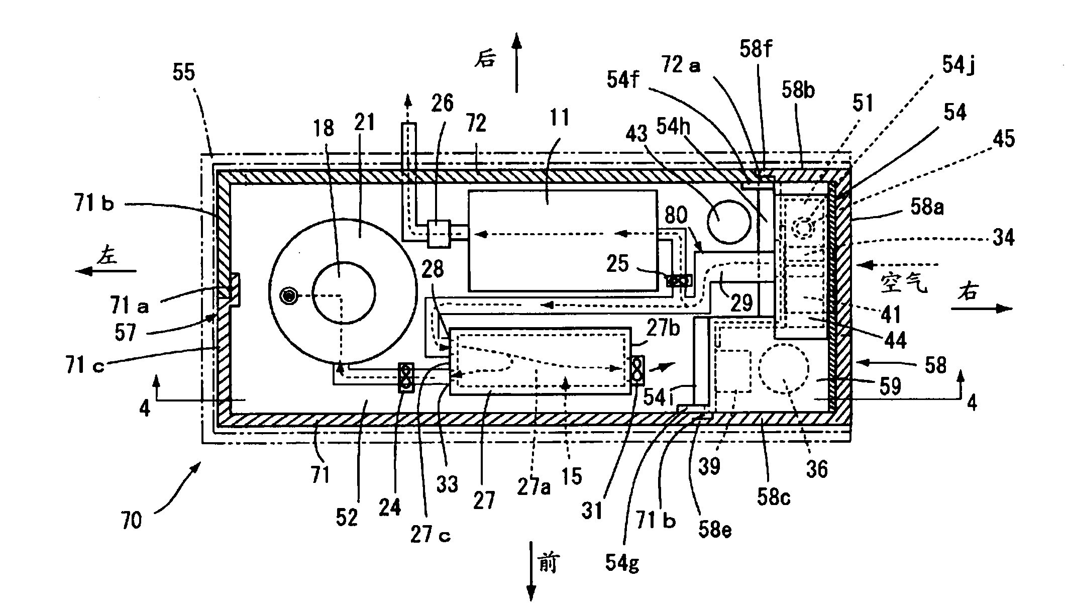
[0021] Next, a first embodiment of the fuel cell system of the present invention will be described with reference to the drawings. figure 1 is a structural block diagram showing the structure of the fuel cell system. This fuel cell system is composed of a fuel cell 11 , a system power supply 12 , a power supply line 13 , auxiliary equipment 14 , an inverter system 15 , a fuel cell system control device 17 , a reformer 21 , a maintenance operation panel 41 , and a circuit breaker 51 . Among them, front, back, left, right, up, down and appended in the text Figure 1 Sincerely.

[0022] The fuel cell 11 is for generating electricity through a chemical reaction of hydrogen and oxygen when supplied with a hydrogen-rich reformed gas and an oxidant gas such as air containing oxygen to output a DC voltage (eg 40V).

[0023] The reformer 21 is used to steam reform the fuel gas and supply the reformed gas rich in hydrogen to the fuel cell 11. Part (hereinafter referred to as CO conv...


PUM


Abstract

Provided is a fuel cell system which can ventilate the interior of a housing through a simple configuration, and can limit suction of combustion gas into the housing even if combustion gas stagnates outside of the housing. A fuel cell system comprises a reformer (21) for producing reformed gas from combustion gas, a fuel cell (11) generating power from reformed gas and oxidizer gas, a cooling passage (80) opening to the outside of a housing (70) and cooling the interior of the housing by introducing cooling air to the housing space in the housing via an inverter system (15), an air blower (31) for introducing cooling air to the cooling passage from the outside of the housing, and a breaker for interrupting the circuit to a power supply line upon occurrence of an abnormality in the fuel cell system or during maintenance, wherein the housing houses the reformer, the fuel cell, the inverter system, the air blower and the breaker in the housing space, and cooling air introduced from the outside of the housing by the air blower is introduced to the housing space while cooling the inverter system, thus maintaining the pressure in the housing space higher than the atmospheric pressure.

Description

technical field [0001] The present invention relates to fuel cell systems. Background technique [0002] Conventionally, as a countermeasure for lowering the temperature inside the casing covering the fuel cell system and releasing combustible gas (for example, hydrogen gas, city gas 13A, etc.) remaining inside the casing through leakage inside the casing, A method disclosed in Patent Document 1 is known as an example of a method of forced ventilation using a ventilation fan. In Patent Document 1, such as Figure 5 As shown in FIG. 8 , air inlets 83 and 84 are provided on one side of the frame, and an exhaust port 90 is provided on one side of the frame. The exhaust port 90 also serves as an exhaust fan. The exhaust fan rotates the fan in the direction of releasing the air inside the frame from the exhaust port to the outside to reduce the pressure inside the frame, so that the air from the air inlet on one side of the frame to the frame The outside air is introduced into ...

Claims


Application Information

Patent Timeline
Patent Type & Authority Applications(China)
IPC IPC(8): H01M8/04H01M8/06
CPCH01M8/0618H01M8/04664H01M8/04955H01M8/04014H01M8/2475Y02E60/50
Inventor 篠田和伸铃村惠司
Owner TOYOTA JIDOSHA KK
Why Eureka
Try Eureka