Automatic adjustment mechanism for main bar position of numerical control square reinforcement cage forming machine

A steel cage forming machine and automatic adjustment technology, which is applied in the direction of manufacturing ring nets, other household appliances, household appliances, etc. by wire, can solve the problems of inability to ensure accurate size, difficulty in improving the speed of seam welding, and large number of molds, etc. The effect of improving seam welding speed and production efficiency, compact structure and large adjustment range

Active Publication Date: 2011-03-02
TJK MACHINERY TIANJIN
View PDF4 Cites 13 Cited by
  • Summary
  • Abstract
  • Description
  • Claims
  • Application Information

AI Technical Summary

Problems solved by technology

The position adjustment mechanism of the main reinforcement in the prior art is not only time-consuming and laborious, the operation is cumbersome, and the number of molds is large, but also limited by the shape of the mold when making the steel cage, the accuracy of the size cannot be guaranteed; It is difficult to increase the speed of rolling welding due to the limitation of the welding wheel walking route

Method used


Image

  • Automatic adjustment mechanism for main bar position of numerical control square reinforcement cage forming machine
  • Automatic adjustment mechanism for main bar position of numerical control square reinforcement cage forming machine
  • Automatic adjustment mechanism for main bar position of numerical control square reinforcement cage forming machine

Examples


Embodiment Construction

[0016] Embodiments of the present invention will be further described below in conjunction with the accompanying drawings.

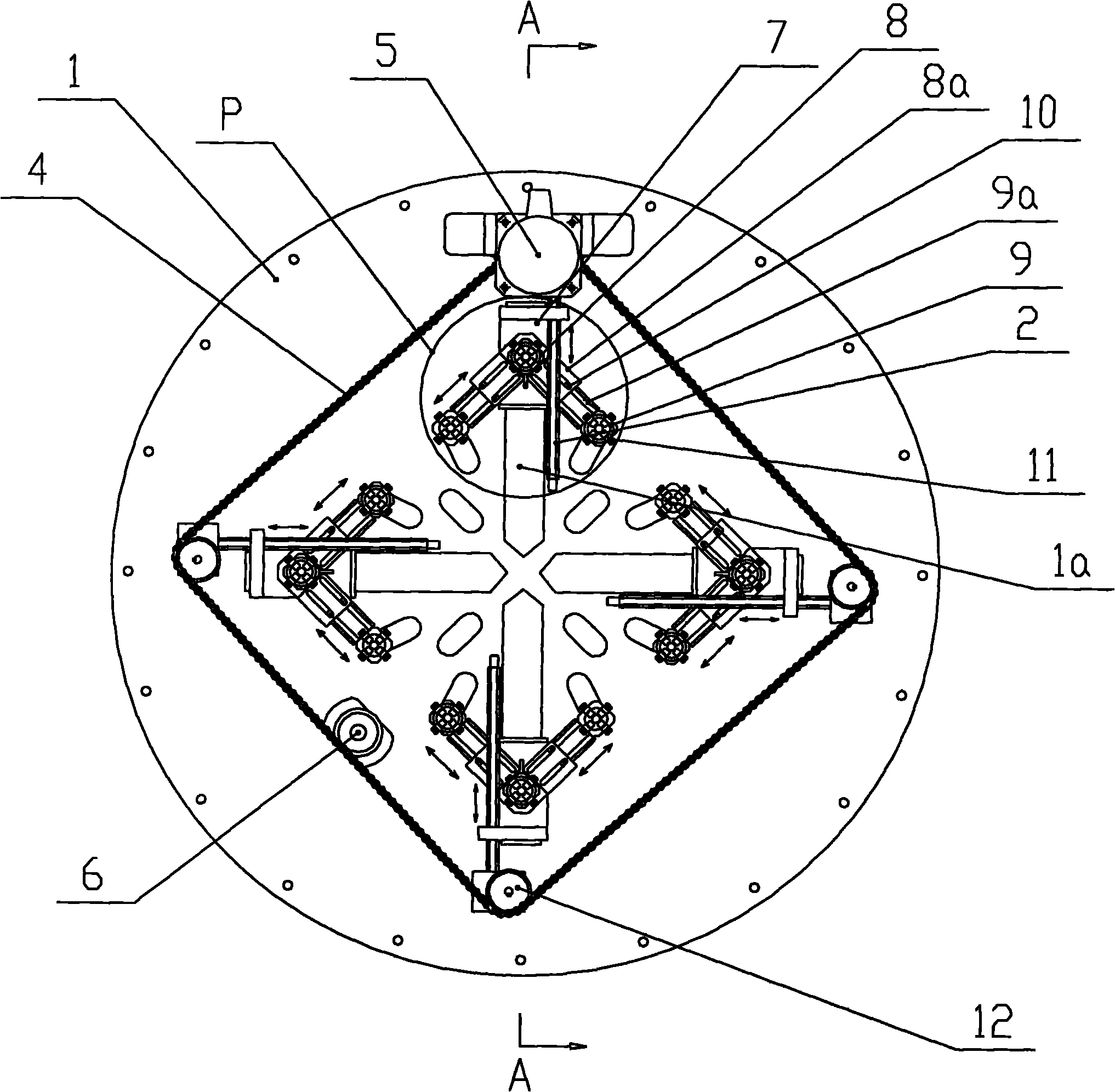
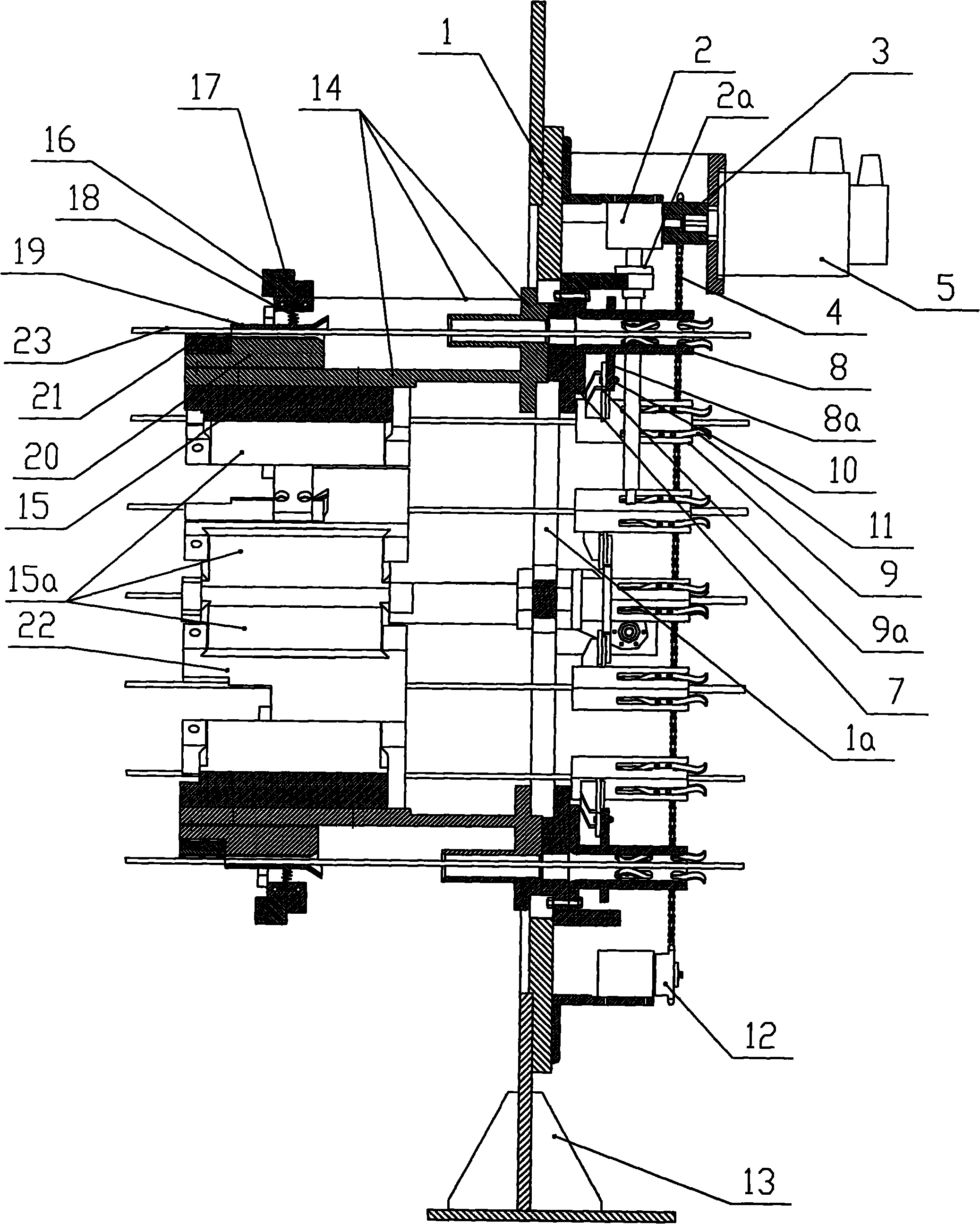
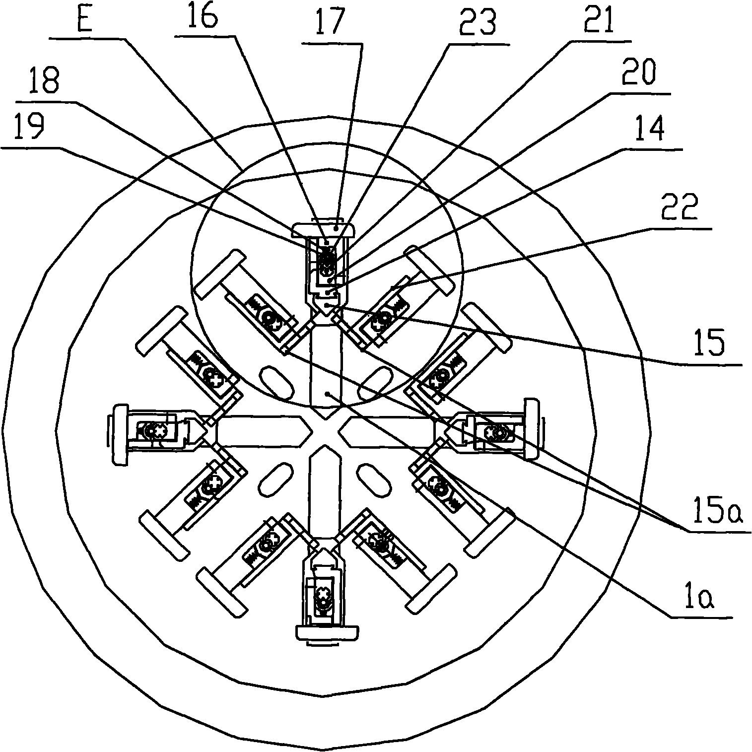
[0017] figure 1 is the front view of the present invention; figure 2 Yes figure 1 Middle A-A sectional view; image 3 Yes figure 1 middle rear view; Figure 4 It is a schematic diagram of the positions of the main bars and stirrups of square steel cages with different specifications for adjustment and processing by the present invention; Figure 5 Yes figure 1 Enlarged view of part p in the middle; Image 6 Yes Figure 5 An enlarged perspective view of , showing the structure of the main rib tube, side wing slides, side rib tube and spring leaf; Figure 7 Yes image 3 Enlarged view of middle E.

[0018] The present invention provides an automatic adjustment mechanism for the position of the main bars of a CNC square steel cage forming machine. The automatic adjustment mechanism for the position of the main bars includes: an adjustment plate 1 ...


PUM


Abstract

The invention discloses an automatic adjustment mechanism for the main bar position of a numerical control square reinforcement cage forming machine. The automatic adjustment mechanism for the main bar position comprises an adjustment plate; a sliding seat is arranged in the slide way of the adjustment plate; a spiral lift driving unit is fixed on the adjustment plate; the drive end of the spiral lift driving unit is connected with the sliding seat and drives the sliding seat to move back and forth along the slide way of the adjustment plate; a main bar penetration pipe is fixed on the sliding seat on one side of the adjustment plate; a conductive sliding seat is fixed on the sliding seat on the other side of the adjustment plate; and a main bar through hole and a conductive electrode are arranged on the conductive sliding seat. The invention has the beneficial effects that: a servo motor controls the positioning; the main bars at four corners can be quickly positioned at a time; the size can be accurately adjusted; and the error of the finished product is low. The side reinforcement can realize fast manual adjustment in place and the adjustment range is large; a numerical control square reinforcement cage forming machine can produce cages of various specifications, realizes multiple functions of one machine and saves the cost. Moreover, the roll welding speed and production efficiency are greatly improved, and the invention has the advantages of simple structure, energy conservation and low cost.

Description

technical field [0001] The invention relates to a numerically controlled square steel cage forming machine, in particular to an automatic adjustment mechanism for the position of main bars of the numerically controlled square steel cage forming machine. Background technique [0002] In recent years, along with economic development, in order to adapt to the construction needs of buildings, highways, etc., a kind of prestressed concrete square pile is widely used, and a large amount of square reinforcement cages are needed to make square piles. The method of making square reinforcement cages has changed from a single row of square stirrup covers welded on the main reinforcement to a CNC square reinforcement cage forming machine for seam welding. [0003] At present, the main reinforcement of the square reinforcement cage produced by the CNC square reinforcement cage forming machine includes four main reinforcements, eight main reinforcements and twelve main reinforcements and ...

Claims


Application Information

Patent Timeline
Patent Type & Authority Applications(China)
IPC IPC(8): B21F31/00
Inventor 陈振东
Owner TJK MACHINERY TIANJIN
Why Eureka
Try Eureka