Method for detecting geometrical motion error of triaxial numerical control equipment

A motion error and error technology, applied in the field of geometric motion error detection, can solve the problems of laser intensity being easily affected by the surrounding environment, the comprehensive measurement accuracy is difficult to reach the micron level, and the machine tool motion accuracy is unstable.

Inactive Publication Date: 2011-03-02
SHANGHAI JIAO TONG UNIV
View PDF6 Cites 21 Cited by
  • Summary
  • Abstract
  • Description
  • Claims
  • Application Information

AI Technical Summary

Problems solved by technology

However, this technology has the following disadvantages: due to the friction between the steel ball and the magnetic recess, the motion accuracy of the measured machine tool is unstable when the feed speed is higher than 10m / min; it can only be measured along the direction of the circular interpolation radius; Due to the deformation of the telescopic rod due to its own weight, the comprehensive measurement accuracy is difficult to reach the micron level; the least square method is used to identify each error component, but the solution is not unique due to the non-full rank of the matrix
However, the problems of this technology are: the installation and light alignment process is troublesome, which affects the measurement accuracy; the laser intensity is easily affected by the surrounding environment; The problem that the solution is not unique due to the non-full rank of the matrix

Method used


Image

  • Method for detecting geometrical motion error of triaxial numerical control equipment
  • Method for detecting geometrical motion error of triaxial numerical control equipment
  • Method for detecting geometrical motion error of triaxial numerical control equipment

Examples


Embodiment Construction

[0066] The embodiments of the present invention are described in detail below. This embodiment is implemented on the premise of the technical solution of the present invention, and detailed implementation methods and specific operating procedures are provided, but the protection scope of the present invention is not limited to the following implementation example.

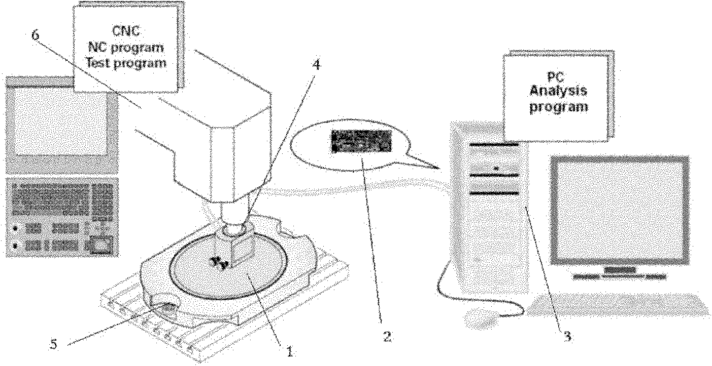
[0067] Such as figure 1 As shown, the step-by-step identification system for the motion error of three-axis numerical control equipment based on plane gratings involved in this embodiment includes: plane detection grating (code disc and reading head) 1, IK220 data acquisition card 2, data processing module 3, Φ20 The tool handle 4, the fixing device 5 and the three-axis numerical control equipment 6, wherein: the plane detection grating reading head 1 is connected to the IK220 data acquisition card 2 to transmit measurement data, and the IK220 data acquisition card 2 is connected to the data processing module 3 to ...


PUM


Abstract

The invention discloses a method for detecting the geometrical motion error of triaxial numerical control equipment in the technical field of mechanical detection. In accordance with the characteristic that a plane grating can measure the linear motion error and the circular motion error of the triaxial numerical control equipment, the method separates 12 error components including the linear error, the position error and the vertical error of a guide rail X, a guide rail Y and a guide rail Z, and then separates 9 rotation angle error components of the three guide rails.

Description

technical field [0001] The invention relates to a method in the technical field of mechanical detection, in particular to a method for detecting geometric motion errors of three-axis numerical control equipment. Background technique [0002] The geometric motion accuracy of three-axis CNC equipment (including three-axis CNC machining centers, three-coordinate measuring machines, etc.) is an important indicator for evaluating its performance, which directly affects the machining (or detection) accuracy, service life and production cost of the workpiece. Improving the geometric motion accuracy of three-axis CNC equipment is the development requirement of the machinery manufacturing industry, and the level of motion accuracy is measured by the size of motion error. Therefore, the measurement of motion error is a key technology in the manufacture and maintenance of CNC equipment. Equipment manufacturers can use the geometric accuracy test results of machine tools or coordinate m...

Claims


Application Information

Patent Timeline
Patent Type & Authority Applications(China)
IPC IPC(8): G01B11/00G01B11/26B23Q17/00
Inventor 杜正春张淑洁郭扬杜月阳杨帆
Owner SHANGHAI JIAO TONG UNIV
Why Eureka
Try Eureka