
Optical fiber grating vibration sensor comprising double cantilever beams with equal strength

A vibration sensor, fiber grating technology, applied in instruments, measuring devices, measuring ultrasonic/sonic/infrasonic waves, etc., can solve the problems of the sensor cannot be used normally, the vibration direction is inconsistent, and the main beam is not easy, so as to improve reliability and stability. , The effect of improving sensitivity and avoiding breakage and damage

Inactive Publication Date: 2011-11-16
NORTHWEST UNIV
View PDF1 Cites 1 Cited by
  • Summary
  • Abstract
  • Description
  • Claims
  • Application Information

AI Technical Summary

Problems solved by technology

Because the vibration of this kind of fiber grating sensor only causes the central wavelength of one grating to drift, the sensitivity is low; and its structure is cylindrical, once it is packaged, it is difficult to determine the direction of the main beam from the appearance, and it is easy to cause the vibration and vibration of the main beam. The vibration direction of the actual object is inconsistent; in addition, the patent does not explain the structure of the beam and the position where the fiber grating is pasted. These factors can easily cause the grating to chirp and cause the sensor to fail to work normally

Method used


Image

  • Optical fiber grating vibration sensor comprising double cantilever beams with equal strength
  • Optical fiber grating vibration sensor comprising double cantilever beams with equal strength
  • Optical fiber grating vibration sensor comprising double cantilever beams with equal strength

Examples


Embodiment 1

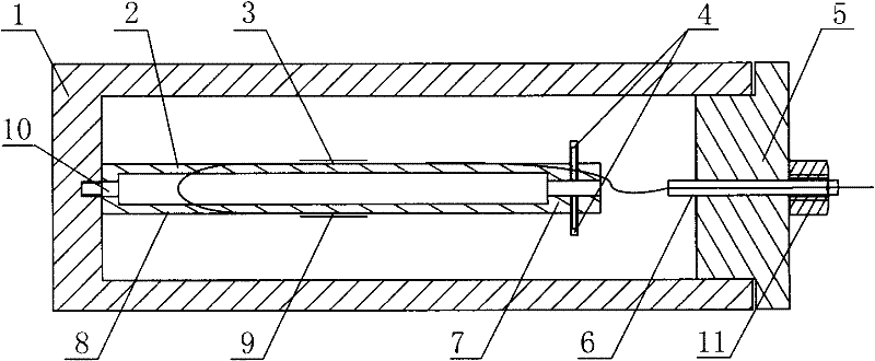
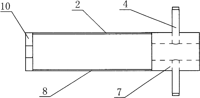
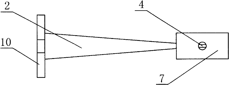
[0016] exist figure 1 Among them, the double equal strength cantilever beam fiber grating vibration sensor of this embodiment consists of a housing 1, an upper cantilever beam 2, an upper sensing fiber grating 3, a cantilever beam limit post 4, a sealing cover 5, an optical fiber protection sleeve 6, and a mass 7. The lower cantilever beam 8, the lower sensing fiber grating 9, the cantilever beam base 10 and the sensor joint 11 are connected to form.

[0017] like figure 1 As shown, on the left side wall of the housing 1 of the cuboid structure, a cantilever beam base 10 is fixedly connected with a threaded fastening connector, and the fixed end of the upper cantilever beam 2 is connected with the upper surface of the cantilever beam base 10. The free end It is integrated with the upper surface of the mass block 7, the fixed end of the lower cantilever beam 8 is integrated with the lower surface of the cantilever beam base 10, and the free end is integrated with the lower sur...

Embodiment 2

[0020] In this embodiment, the upper cantilever beam 2 and the lower cantilever beam 8 are made of stainless steel, the upper sensing fiber grating 3 and the lower sensing fiber grating 9 are germanium-doped fiber gratings, and the upper sensing fiber grating 3 and the lower sensing fiber grating 9 are The wavelength is 1620nm. Other components and the coupling relationship of the components are the same as in Embodiment 1.

Embodiment 3

[0022] In this embodiment, the upper cantilever beam 2 and the lower cantilever beam 8 are made of stainless steel, the upper sensing fiber grating 3 and the lower sensing fiber grating 9 are germanium-doped fiber gratings, and the upper sensing fiber grating 3 and the lower sensing fiber grating 9 are The wavelength is 1550nm. Other components and the coupling relationship of the components are the same as in Embodiment 1.


PUM


Abstract

The invention relates to an optical fiber grating vibration sensor comprising double cantilever beams with equal strength, a cantilever beam base is arranged on the left side in a housing, the fixing ends of the upper sheet-like cantilever beam and the lower sheet-like cantilever beam, which are parallel to each other are connected with the cantilever beam base into a whole, the free ends are arranged on the upper side surface and the lower side surface of a mass block, cantilever beam position-limiting columns which are vertical to the surfaces are arranged on the surfaces which are respectively parallel to the plane of the upper cantilever beam and the plane of the lower cantilever beam of the mass block, a sealing cover which is equipped with a sensor joint on the outer side is arranged at the open end of the housing, an optical fiber protective casing penetrating the center of the sealing cover and the center of the sensor joint is arranged on the sealing cover, the ratio of the width of the fixing ends of the upper cantilever beam and the lower cantilever beam to the width of the free ends is 5 at least, an upper sensing optical fiber grating is arranged on the upper surface of the upper cantilever beam, a lower sensing optical fiber grating is arranged on the lower surface of the lower cantilever beam, and the series connection output end of the upper sensing optical fiber grating and the lower sensing optical fiber grating penetrates out of the optical fiber protective casing. The optical fiber grating vibration sensor has good sensitivity, reliability and stability.

Description

technical field [0001] The invention belongs to the technical field of fiber grating sensors, in particular to a fiber grating vibration sensor used for measuring the vibration amplitude and frequency of an object. Background technique [0002] The fiber grating sensor uses changes in external physical quantities such as stress, strain, temperature, etc. to cause changes in the effective refractive index of the optical fiber or the grating period, which leads to changes in the center wavelength of the grating reflection. The external physical quantity is obtained by detecting the change in the center wavelength of the grating reflection. The change. Compared with traditional electrical vibration sensors, electrical vibration sensors output weak electrical signals, which are susceptible to electromagnetic interference. They are not suitable for working in strong electromagnetic field environments such as large electromechanical equipment, and cannot be used for long-distance ...

Claims


Application Information

Patent Timeline
Patent Type & Authority Patents(China)
IPC IPC(8): G01H9/00
Inventor 乔学光高宏傅海威贾振安刘钦朋
Owner NORTHWEST UNIV
Learn More