Electronic ice fan

An ice blower and electronic technology, which is applied in mechanical equipment, electrostatic spraying devices, machines/engines, etc., can solve the problems such as small amount of fog output by the air cooler, blowing air is not cool, small amount of fog output is not cool, etc.

Inactive Publication Date: 2011-03-09
林美利
View PDF6 Cites 104 Cited by
  • Summary
  • Abstract
  • Description
  • Claims
  • Application Information

AI Technical Summary

Problems solved by technology

[0005] 1. The purpose of this creation is to provide a cooling fan device that solves the problem that the air blowing is not cool when the amount of fog is small, and the axial flow fan, the flow increasing ring and the mist generator

Method used


Image

  • Electronic ice fan
  • Electronic ice fan
  • Electronic ice fan

Examples


Embodiment Construction

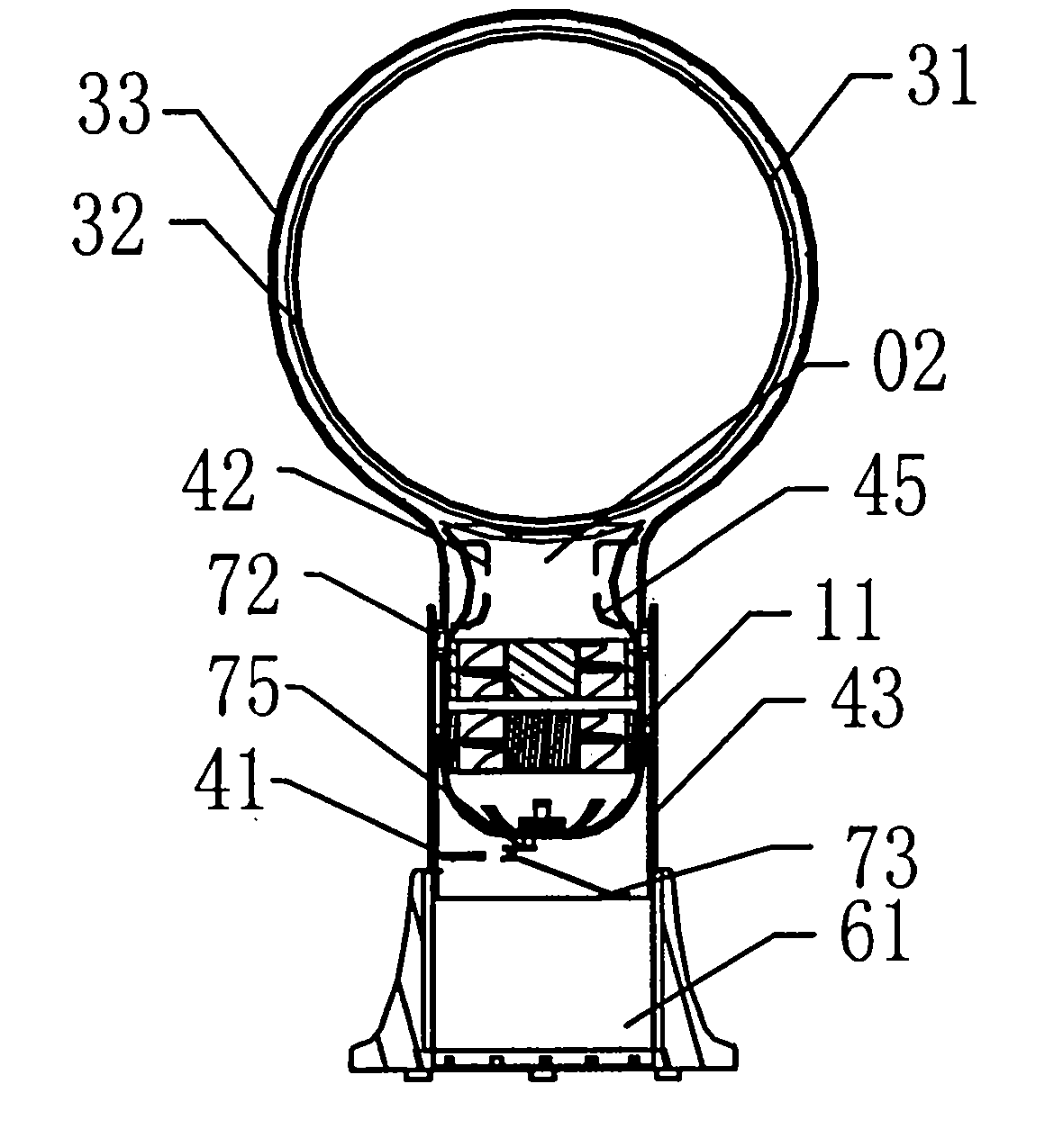
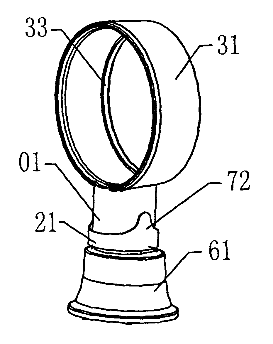
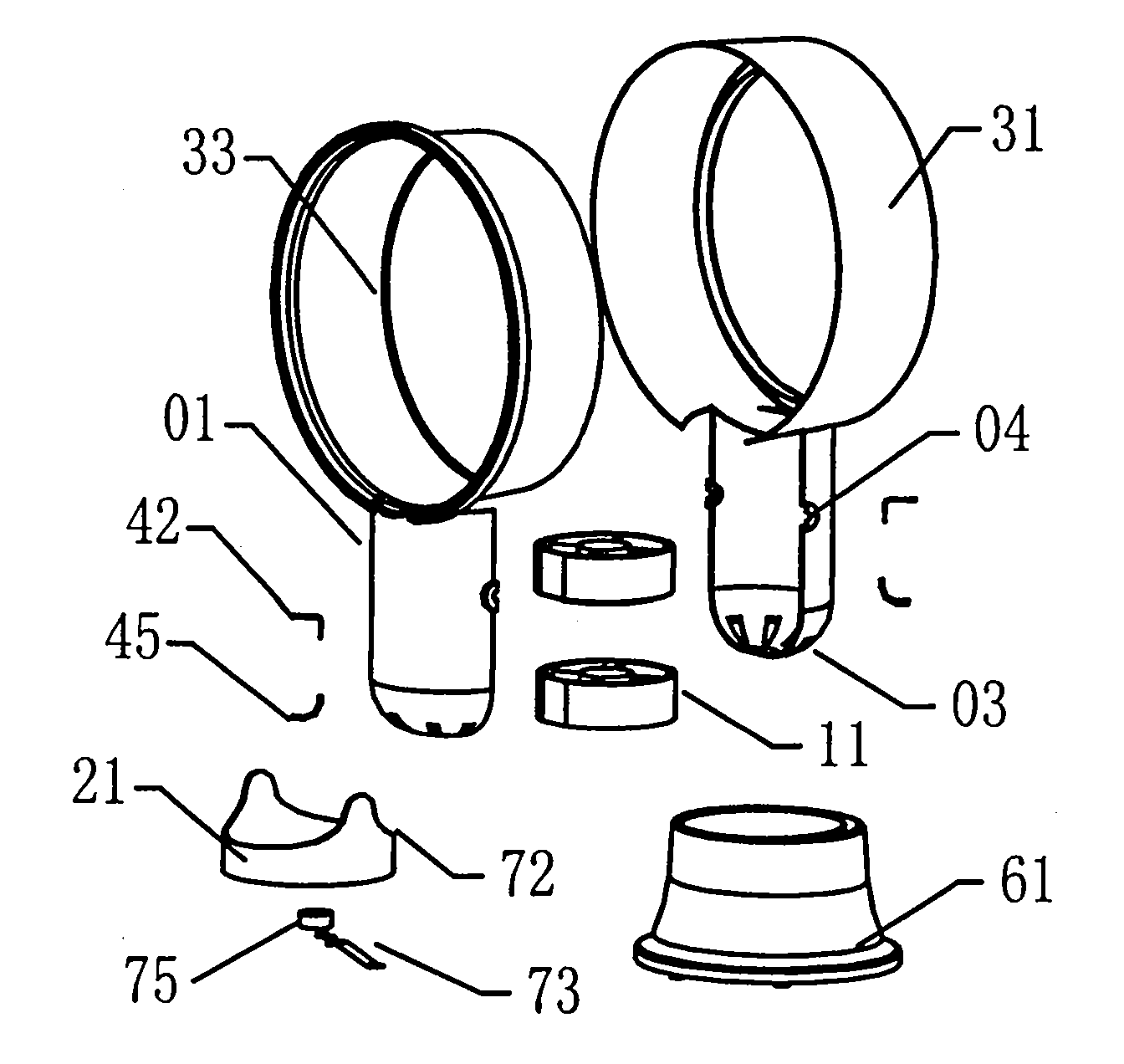
[0035] 1. The structure of this case is as follows: figure 1 : Sectional view of the structure of this creation and Figure 2: Appearance of this creation. Body seat 01, an axial flow fan 11, a refrigerator 61, a mist generator 51, a rotator 71 and a flow-increasing ring 31, a refrigerator 61 is installed under the body seat 01, and a booster shaft is housed in the body seat 01 The flow fan 11 has an air suction port 03 below the axial flow fan 11, and an annular flow-increasing ring 31 is installed on the top of the body seat. There is a mist-exciting tube 02 on the top, and a mist-exciting device is installed inside the mist-exciting tube 02. The mist-exciting device 51 is connected to the refrigerator 61 below, and the mist-exciting pipe is connected to the flow-increasing ring 31 above. 51. The pressurized axial flow fan 11 sucks in air from the air suction port 03 below, forming a high-pressure air flow through the mist-exciting tube, and the high-pressure air flow blows...


PUM


Abstract

The invention discloses an electronic ice fan. An ice containing box is arranged below a body seat; a pressure increasing axial flow fan is arranged in the body seat; a suction port is formed below the axial flow fan; an annular flow increasing ring is arranged above the body seat; a circulation channel and a jet flow port are formed in the flow increasing ring; a mist stimulation pipe is arranged above the pressure increasing axial flow fan; a mist stimulator is arranged on the lower part of the mist stimulation pipe and connected with the ice containing box below; the mist stimulation pipe is communicated with the pressure increasing ring above; the ice water in the ice containing box flows to the mist stimulator; the pressure increasing axial flow fan sucks air from the lower suction opening to form high-pressure air flow; the high-pressure air flow flows through the mist stimulation pipe and blows the water mist of the mist stimulator through the circulation channel to form ice mist at the jet flow port of the flow increasing ring; and the ice mist is immediately gasified into ice-cold air. The invention aims at providing an air cooler device which solves the problems of small mist amount and non-cool air of the air cooler by using the axial flow fan, the flow increasing ring and the mist stimulator; and moreover, as no fan blade is arranged in the flow increasing ring, the effects of large mist amount and cool air of a bladeless ice fan are realized.

Description

Technical field [0001] The new structure relates to a cooling fan device with ice-cold mist spraying, in particular to a spray cooling fan device with a mist exciter and a flow-increasing ring. The ice water in the refrigerator flows to the mist generator, and the supercharged axial flow fan sucks in air from the lower suction port, forming high-pressure air to flow through the shrink tube, and the high-pressure air flows the water mist from the mist generator through the circular flow channel from the spray of the flow-increasing ring The icy mist blows out from the orifice, and the icy mist quickly turns into icy wind. Background technique [0002] General mist-cooled air coolers, such as Figure 17 : Structural diagram of conventional air cooler and Figure 18 : Three-dimensional exploded view of a conventional air cooler. Including fan 14, water tank 65 and evaporation filter 55, water tank 65, bottom base 24 and wheels 34 are installed under the body shell 05, water p...

Claims


Application Information

Patent Timeline
IPC IPC(8): F24F5/00F24F13/32B05B5/00F04D25/08
CPCF04D25/08F04F5/16F04F5/462
Inventor 林美利
Owner 林美利
Why Eureka
Try Eureka