Deep reactive ion etching method and gas-flow control device thereof

A deep reaction ion and gas flow technology, applied in semiconductor/solid-state device manufacturing, electrical components, circuits, etc., can solve the problems of reduced smoothness of the side walls of through holes, reduced etching efficiency, etc., to achieve good smoothness and reduce switching Time, the effect of improving etching efficiency

Active Publication Date: 2011-03-23
ADVANCED MICRO FAB EQUIP INC CHINA
View PDF4 Cites 24 Cited by
  • Summary
  • Abstract
  • Description
  • Claims
  • Application Information

AI Technical Summary

Problems solved by technology

[0007] The technical problem to be solved by the present invention is to avoid the problem of reduced smoothness of the side ...

Method used


Image

  • Deep reactive ion etching method and gas-flow control device thereof
  • Deep reactive ion etching method and gas-flow control device thereof
  • Deep reactive ion etching method and gas-flow control device thereof

Examples


Embodiment Construction

[0022] In order to make the object, technical solution and advantages of the present invention clearer, the present invention will be further described in detail below in conjunction with the accompanying drawings.

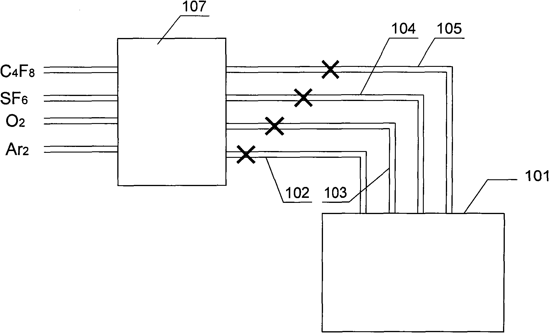
[0023] Figure 4 Shown is a schematic diagram of the gas flow control device provided by the present invention. Such as Figure 4 As shown, the gas flow device includes a chamber 301, a pipeline 302 for passing Ar gas, and a pipeline for passing O 2 Gas pipeline 303, through SF 6 Gas pipeline 304, through C 4 f 8 Gas pipeline 305, MFC and MFC control module 310, the gas flow control device is used for gas flow control in the deep reactive ion etching process, the wafer to be etched is placed in the chamber 301, and the pipelines 302, 303 MFC312, 313, 314, 315 are respectively set in , 304, 305, and the MFC control module 310 can control MFC312, 313, 314, 315 at the same time. Real-time control of the flow, therefore, the gas flow flowing through each pipelin...


PUM


Abstract

A deep reactive ion etching method belongs to the technical field of manufacturing of semiconductors. The method comprises an etching step and a polymer-depositing step which are alternately performed, wherein the conversion between a first process condition employed by the etching step and a second process condition employed by the polymer-depositing step is realized by a gradually changed conversion method. The side wall of a deep through hole etched by the deep reactive ion etching method has good smoothness; and the etching efficiency of the method is high.

Description

technical field [0001] The invention belongs to the technical field of semiconductor manufacturing, in particular to a reactive ion etching (Reactive Icon Etching, RIE) technology, in particular to a deep reactive ion etching (De-coupled RIE, DRIE) method and a gas flow control device thereof. Background technique [0002] In the field of semiconductor manufacturing technology, in fields such as MEMS (Micro-Electro-Mechanical Systems, micro-electro-mechanical systems) and 3D packaging technology, it is usually necessary to etch deep via holes in materials such as silicon. For example, in bulk silicon etching technology, deep through-silicon-vias (Through-Silicon-Via, TSV) have a depth of hundreds of microns and an aspect ratio greater than 10, and deep reactive ion etching is usually used to etch bulk silicon. form. [0003] figure 1 Shown is a schematic diagram of the deep reactive ion etching method in the prior art. In the prior art, the deep reactive ion etching of TS...

Claims


Application Information

Patent Timeline
IPC IPC(8): C23F1/12H01L21/3065
Inventor 尹志尧吴万俊刘鹏
Owner ADVANCED MICRO FAB EQUIP INC CHINA
Why Eureka
Try Eureka