Supercharge Your Innovation With Domain-Expert AI Agents!

Rotary pipeline dredging cleaner

A rotary type and cleaning device technology is applied in the field of sewer pipeline dredging equipment, which can solve the problems of inability to dredging and cleaning sludge pipelines, manual waste, affecting work efficiency, etc. Effect

Inactive Publication Date: 2011-03-30
淮安市苏通市政机械有限公司
View PDF3 Cites 17 Cited by
  • Summary
  • Abstract
  • Description
  • Claims
  • Application Information

AI Technical Summary

Problems solved by technology

[0003] At present, the pipe dredging cleaners on the market are generally a kind of conical flushing head, which is provided with a water jet hole on its rear end face. Driven by force, the conical head arches forward. If it encounters compacted silt, or silt mixed with sand, salt, etc., if the conical head arches into it, there will be a situation where it cannot move forward and cannot retreat. In order to improve work efficiency, it is impossible to effectively dredge and clean this type of sludge pipeline. Sometimes it is even necessary to break the road or demolish some buildings to dredge the pipeline.
For another example, when encountering some oil stains, construction waste or roots protruding from green tree trunks, the existing flushing head cannot dredge and flush them. For such pipeline blockages, only by breaking the road surface or demolishing buildings can dredging be carried out. and cleaning
It is conceivable how much inconvenience this will bring to people's lives and urban traffic, and how much resource waste and artificial waste will be caused.

Method used


Image

  • Rotary pipeline dredging cleaner
  • Rotary pipeline dredging cleaner
  • Rotary pipeline dredging cleaner

Examples


Embodiment 1

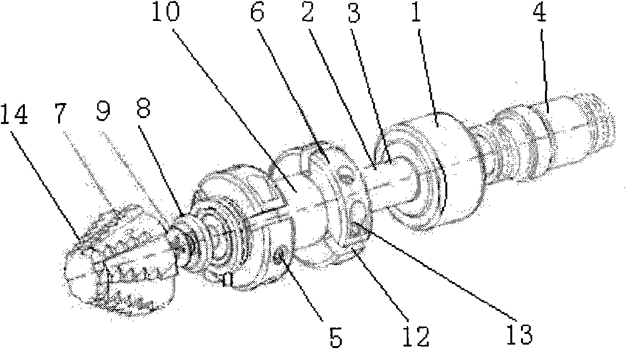
[0017] Such as figure 1 As shown, the present invention includes a pipe shaft 2 provided with a water jet seat 1, the pipe shaft 2 is provided with a water outlet 3, and the end of the pipe shaft 2 water jet seat 1 is provided with a connecting head 4 with a high-pressure rubber hose (the water jet seat It is threaded with the connecting head). It also includes a rotating sleeve 6 provided with a water injection hole 5 and a punching head 7, and the rotating sleeve 6 is movably connected to the pipe shaft 2 (limited by tightening the limit pad 8 and the bolt 9). The inner peripheral surface of the rotating sleeve 6 is provided with a ring of water inlet grooves (not shown in the figure), and the water inlet grooves are matched and communicated with the water outlet holes 3 on the pipe shaft 2 . The piercing head 7 is threadedly connected to the rotary sleeve 6 .

[0018] Such as figure 1 , 2 As shown in , 3, two rotating sleeves 6 are provided, and the two are connected by...

Embodiment 2

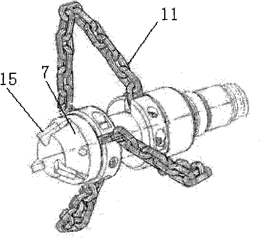
[0024] Such as figure 2 As shown, the piercing head 7 is a circular truncated body, and blades 15 are equally divided on the peripheral surface. All the other implementations are as in Example 1.

Embodiment 3

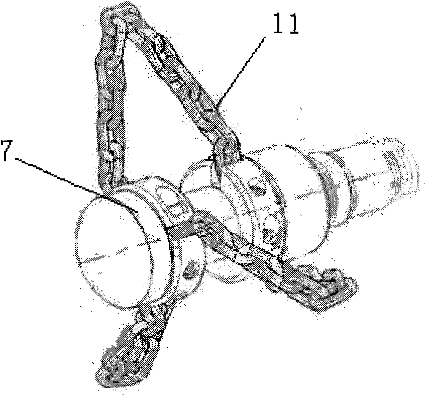
[0026] Such as image 3 As shown, the piercing head 7 is a circular frustum, and the peripheral surface is a smooth surface. All the other implementations are as in Example 1.

[0027] The piercing heads 7 of the three structures in Embodiments 1, 2, and 3 can be assembled as required.


PUM


Abstract

The invention discloses a rotary pipeline dredging cleaner, which comprises a tubular shaft provided with a water jet seat, wherein the tubular shaft is provided with water outlets; the end positioned at the water jet seat of the tubular shaft is provided with a communicating head communicated with a high-pressure rubber tube; the cleaner also comprises rotary sleeves with water jet holes and a punching head, wherein the rotary sleeves are movably connected with the tubular shaft, the inner circumferential surface of the rotary sleeve is provided with a circle of water inlet grooves, and the water inlet grooves are matched with the water outlets on the tubular shaft; and the punching head are connected on the rotary sleeves. The number of the rotary sleeves is at least two, and the two rotary sleeves are connected through a connecting pipe. The rotary sleeves are provided with cutting pieces, and the cutting pieces and the water jet holes are equally arranged on the circumferences of the rotary sleeves. The cleaner can quickly advance in a pipeline; and during punching and dredging, the punching head drills, cuts and crushes barriers, and a chain twists and breaks the barriers so as to fulfill the purposes of punching, dredging and cleaning. The cleaner has strong practicability and practical aspects, and can meet the pipeline dredging and cleaning requirements of different pollutant blockage.

Description

technical field [0001] The invention relates to equipment for dredging sewer pipes, in particular to a cleaner for dredging sewer pipes. Background technique [0002] The pipe dredging cleaner is a key part of the special vehicle (sewer combined dredging vehicle, high-pressure cleaning vehicle) to carry out the dredging and flushing operation of the sewer pipe. In recent years, with the development of social economy, people have higher and higher requirements for living environment, working environment and urban sanitation. Among them, the smooth flow of sewer is an important aspect to solve the above problems, and its regular maintenance and cleaning are essential. Therefore, requirements are put forward for the performance of the pipeline dredging cleaner, not only requiring it to have higher efficiency, but also requiring it to be able to effectively pierce through, dredge and flush various sludge pipelines. [0003] At present, the pipe dredging cleaners on the market a...

Claims


Application Information

Patent Timeline
IPC IPC(8): E03F9/00E03F7/10
Inventor 刘敬福王连陈联艮丁红兵吕建强
Owner 淮安市苏通市政机械有限公司
Features
  • R&D
  • Intellectual Property
  • Life Sciences
  • Materials
  • Tech Scout
  • Unparalleled Data Quality
  • Higher Quality Content
  • 60% Fewer Hallucinations
Learn More