
Transverse wind driven generator

A technology of wind power generators and generators, applied in the direction of wind power generator components, wind power engines, wind power motor combinations, etc., can solve problems such as economic losses of enterprises, shortage of power consumption, and unused area, so as to alleviate the shortage of power consumption, The effect of low production cost and simple structure

Inactive Publication Date: 2011-03-30
庄兴炎
View PDF3 Cites 2 Cited by
  • Summary
  • Abstract
  • Description
  • Claims
  • Application Information

AI Technical Summary

Problems solved by technology

This type of generator needs to be installed on a relatively open ground, and there must be no high-rise buildings nearby, so this type of wind turbine cannot be installed in densely built cities.
In addition, the wind conditions on the roof are generally better, but the wind resources on this part are basically not utilized, and the roofs of houses are basically only equipped with solar water heaters, and other areas are not utilized
On the other hand, the current electricity consumption in various regions of our country is soaring, especially during the peak period of electricity consumption in summer. The country's power supply has already been in short supply in most areas. Power cuts must be cut off, which will bring huge economic losses to enterprises and have a certain impact on the country's economic development.

Method used

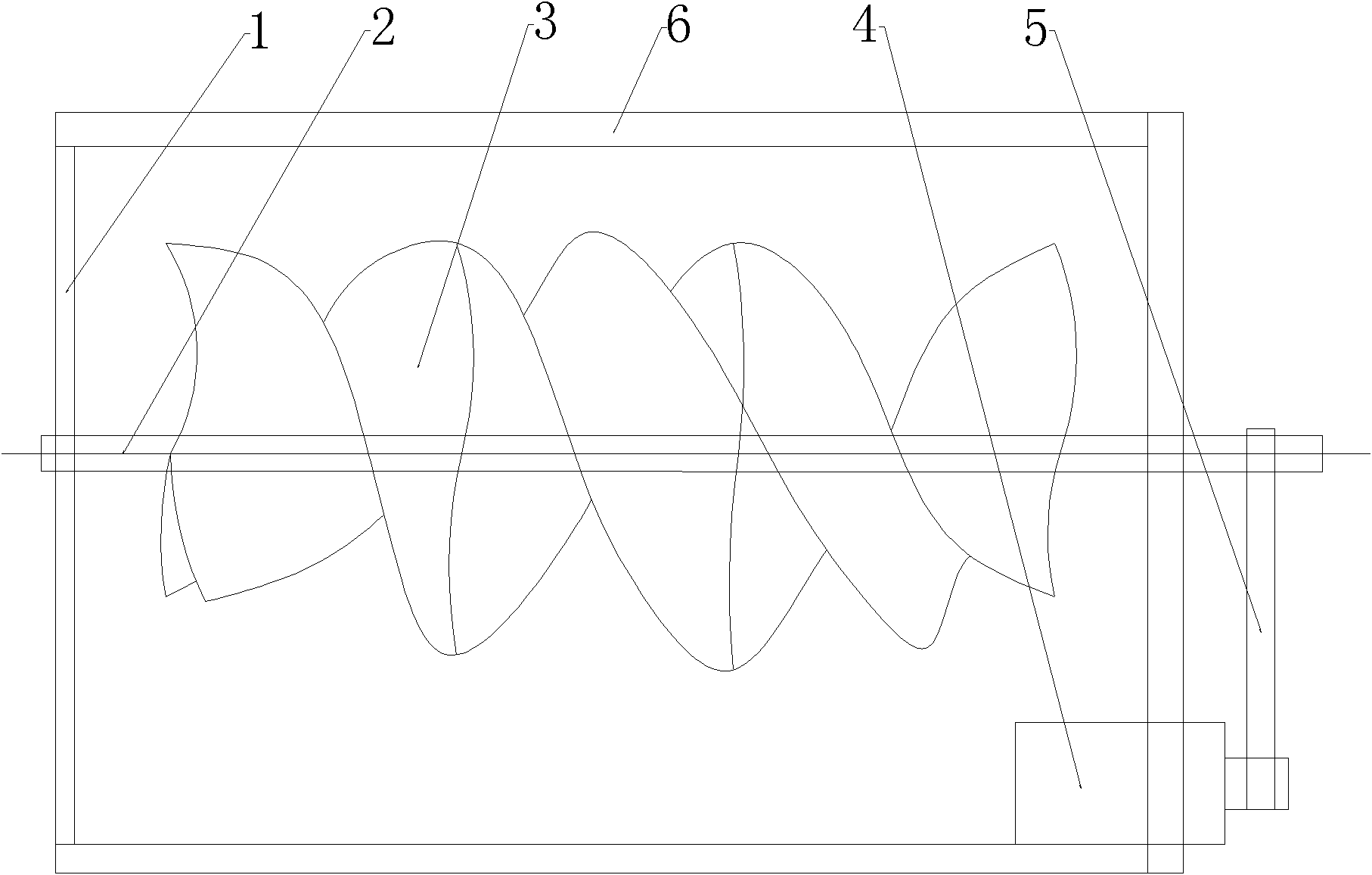
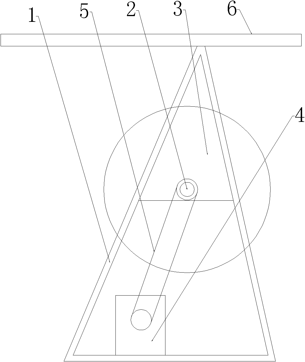

Image

  • Transverse wind driven generator
  • Transverse wind driven generator
  • Transverse wind driven generator

Examples


Embodiment 1

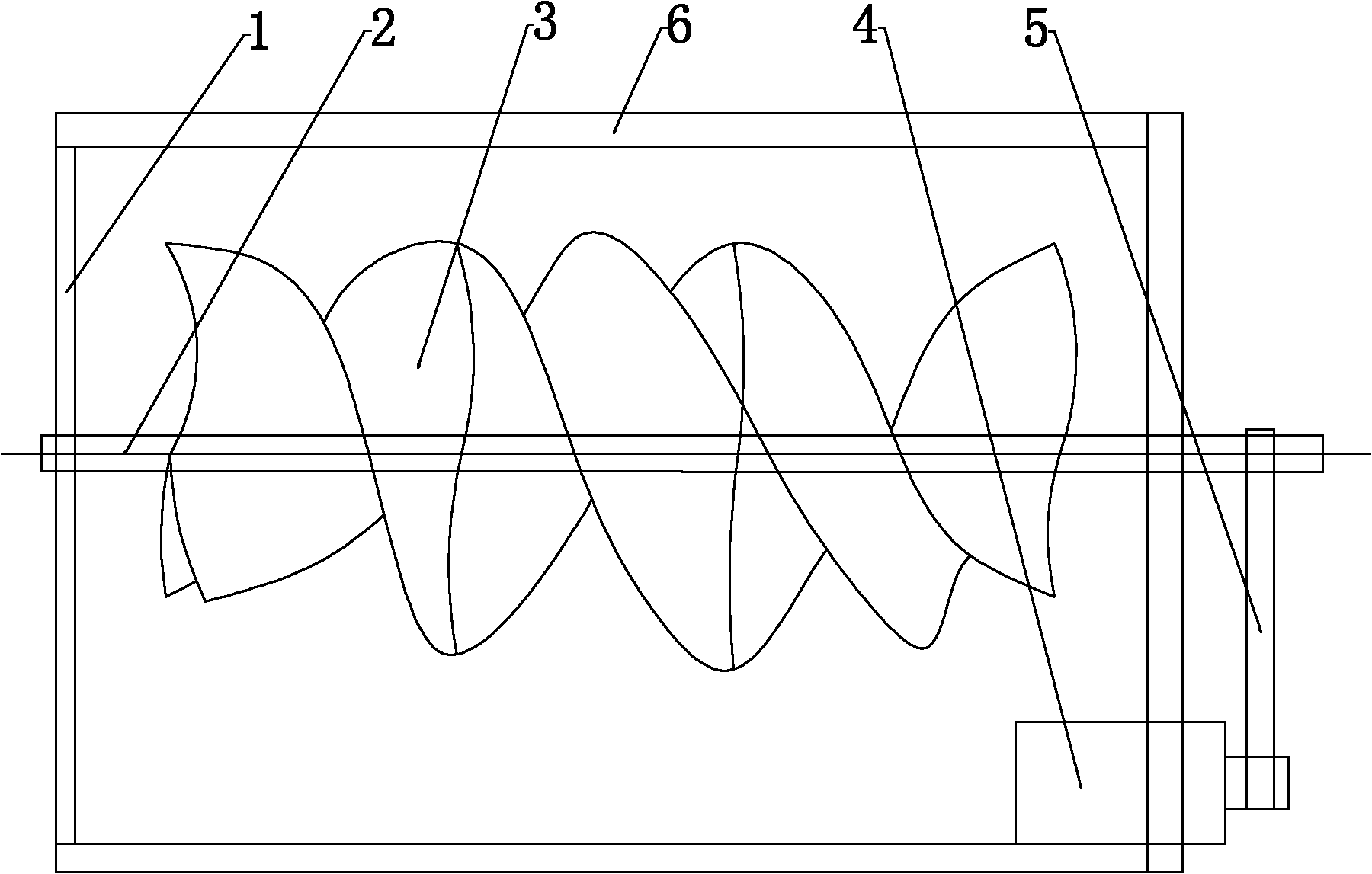
[0014] Such as figure 1 , figure 2 As shown, the horizontal wind power generator described in this embodiment mainly includes a combined frame 1, fan blades 3 and a generator 4, a main shaft 2 is arranged in the middle of the combined frame 1, and the fan blades 3 are arranged on On the main shaft 1, the generator 4 is set on one side of the combined frame 1, the generator 4 is connected to the main shaft 2 through the transmission mechanism 5, the number of fan blades 3 is 2-4 pieces, and the fan blades 3 are evenly arranged on the main shaft in a spiral shape. 2, a snow shield 6 is arranged on the combined frame 1 top.

Embodiment 2

[0016] In the horizontal wind power generator described in this embodiment, two combined racks 1 are arranged side by side, and the wind blades 3 on the combined rack 1 have opposite helical directions. Machine 4 is connected.

Embodiment 3

[0018] The horizontal wind power generator described in this embodiment is provided with a solar panel on the combined frame 1, and utilizes solar energy and wind energy to convert them into electric energy to increase a relatively large power.


PUM


Abstract

The invention provides a transverse wind driven generator which comprise a combined rack, fan blades and a generator, wherein the middle of the combined rack is provided with a main shaft; the fan blades are arranged on the main shaft; the generator is arranged at one side of the combined rack and is connected with the main shaft by a transmission mechanism; and the number of the fan blades is 2-4 and the fan blades are evenly distributed on the main shaft in a screw type. The transverse wind driven generator can be arranged on a roof due to the small structure, so that the stronger wind power resource and the area resource which is difficult in use on the roof can be completely utilized to be converted into electric energy which is lack relatively in the country. The vertical wind driven generator can not be arranged in the city with dense buildings, so that the wind power is not used effectively. The transverse wind driven generator can be arranged on the roof, and can be used for converting the wind power into the electric energy, thus the problem of lack power supply in the city can be relieved, and the problem that enterprises are switched out to limit the power supply at the peak of the power supply at the same time. In addition, the transverse wind driven generator has the advantages of great significance, high practical applicability and low production cost.

Description

technical field [0001] The invention relates to the wind power generation industry, in particular to a horizontal wind power generator. Background technique [0002] At present, wind power generators in the industry are generally relatively large vertical wind power generators. This type of generator needs to be installed on a relatively open ground, and there must be no high-rise buildings nearby, so this type of wind turbine cannot be installed in densely built cities. In addition, generally the wind conditions on the roof are relatively good, but now this part of the wind resource is basically not used, and now the roof of the house is basically only equipped with solar water heaters, and other areas are not used. On the other hand, the current electricity consumption in various regions of our country is soaring, especially during the peak period of electricity consumption in summer. The country's power supply has already been in short supply in most areas. Power cuts m...

Claims


Application Information

Patent Timeline
Patent Type & Authority Applications(China)
IPC IPC(8): F03D9/00F03D1/06F03D11/00F03D80/00
CPCY02B10/30Y02E10/725Y02E10/721Y02E10/722Y02E10/72Y02P70/50Y02P80/20
Inventor 庄兴炎
Owner 庄兴炎
Learn More